

4.5 Applications in the Numerical Analyses
97
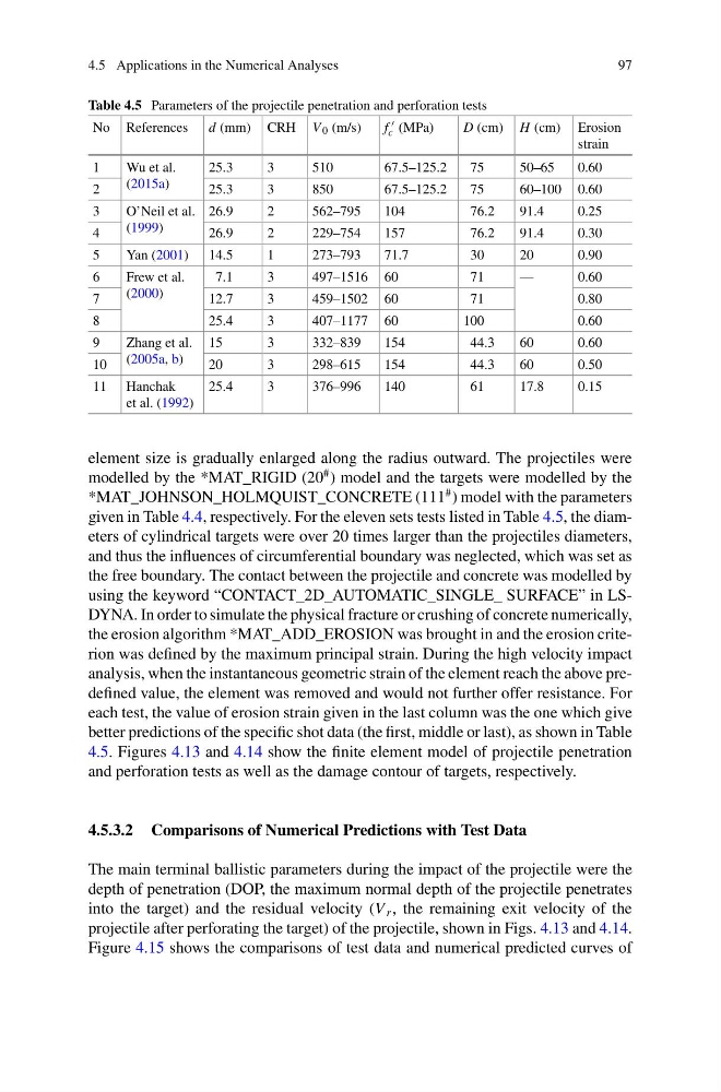
Table 4.5 Parameters of the projectile penetration and perforation tests
No References d (mm) CRH V 0 (m/s)
f
c (MPa)
D (cm) H (cm) Erosion
strain
1
Wu et al.
(2015a)
25.3
3
510
67.5–125.2
75
50–65
0.60
2
25.3
3
850
67.5–125.2
75
60–100 0.60
3
O’Neil et al.
(1999)
26.9
2
562–795
104
76.2
91.4
0.25
4
26.9
2
229–754
157
76.2
91.4
0.30
5
Yan (2001) 14.5
1
273–793
71.7
30
20
0.90
6
Frew et al.
(2000)
7.1
3
497–1516 60
71
—
0.60
7
12.7
3
459–1502 60
71
0.80
8
25.4
3
407–1177 60
100
0.60
9
Zhang et al.
(2005a, b)
15
3
332–839
154
44.3
60
0.60
10
20
3
298–615
154
44.3
60
0.50
11 Hanchak
et al. (1992)
25.4
3
376–996
140
61
17.8
0.15
element size is gradually enlarged along the radius outward. The projectiles were
modelled by the *MAT_RIGID (20
# ) model and the targets were modelled by the
*MAT_JOHNSON_HOLMQUIST_CONCRETE (111
# ) model with the parameters
given in Table 4.4, respectively. For the eleven sets tests listed in Table 4.5, the diameters of cylindrical targets were over 20 times larger than the projectiles diameters,
and thus the influences of circumferential boundary was neglected, which was set as
the free boundary. The contact between the projectile and concrete was modelled by
using the keyword “CONTACT_2D_AUTOMATIC_SINGLE_ SURFACE” in LSDYNA. In order to simulate the physical fracture or crushing of concrete numerically,
the erosion algorithm *MAT_ADD_EROSION was brought in and the erosion criterion was defined by the maximum principal strain. During the high velocity impact
analysis, when the instantaneous geometric strain of the element reach the above predefined value, the element was removed and would not further offer resistance. For
each test, the value of erosion strain given in the last column was the one which give
better predictions of the specific shot data (the first, middle or last), as shown in Table
4.5. Figures 4.13 and 4.14 show the finite element model of projectile penetration
and perforation tests as well as the damage contour of targets, respectively.
4.5.3.2 Comparisons of Numerical Predictions with Test Data
The main terminal ballistic parameters during the impact of the projectile were the
depth of penetration (DOP, the maximum normal depth of the projectile penetrates
into the target) and the residual velocity (V r , the remaining exit velocity of the
projectile after perforating the target) of the projectile, shown in Figs. 4.13 and 4.14.
Figure 4.15 shows the comparisons of test data and numerical predicted curves of
97
Table 4.5 Parameters of the projectile penetration and perforation tests
No References d (mm) CRH V 0 (m/s)
f
c (MPa)
D (cm) H (cm) Erosion
strain
1
Wu et al.
(2015a)
25.3
3
510
67.5–125.2
75
50–65
0.60
2
25.3
3
850
67.5–125.2
75
60–100 0.60
3
O’Neil et al.
(1999)
26.9
2
562–795
104
76.2
91.4
0.25
4
26.9
2
229–754
157
76.2
91.4
0.30
5
Yan (2001) 14.5
1
273–793
71.7
30
20
0.90
6
Frew et al.
(2000)
7.1
3
497–1516 60
71
—
0.60
7
12.7
3
459–1502 60
71
0.80
8
25.4
3
407–1177 60
100
0.60
9
Zhang et al.
(2005a, b)
15
3
332–839
154
44.3
60
0.60
10
20
3
298–615
154
44.3
60
0.50
11 Hanchak
et al. (1992)
25.4
3
376–996
140
61
17.8
0.15
element size is gradually enlarged along the radius outward. The projectiles were
modelled by the *MAT_RIGID (20
# ) model and the targets were modelled by the
*MAT_JOHNSON_HOLMQUIST_CONCRETE (111
# ) model with the parameters
given in Table 4.4, respectively. For the eleven sets tests listed in Table 4.5, the diameters of cylindrical targets were over 20 times larger than the projectiles diameters,
and thus the influences of circumferential boundary was neglected, which was set as
the free boundary. The contact between the projectile and concrete was modelled by
using the keyword “CONTACT_2D_AUTOMATIC_SINGLE_ SURFACE” in LSDYNA. In order to simulate the physical fracture or crushing of concrete numerically,
the erosion algorithm *MAT_ADD_EROSION was brought in and the erosion criterion was defined by the maximum principal strain. During the high velocity impact
analysis, when the instantaneous geometric strain of the element reach the above predefined value, the element was removed and would not further offer resistance. For
each test, the value of erosion strain given in the last column was the one which give
better predictions of the specific shot data (the first, middle or last), as shown in Table
4.5. Figures 4.13 and 4.14 show the finite element model of projectile penetration
and perforation tests as well as the damage contour of targets, respectively.
4.5.3.2 Comparisons of Numerical Predictions with Test Data
The main terminal ballistic parameters during the impact of the projectile were the
depth of penetration (DOP, the maximum normal depth of the projectile penetrates
into the target) and the residual velocity (V r , the remaining exit velocity of the
projectile after perforating the target) of the projectile, shown in Figs. 4.13 and 4.14.
Figure 4.15 shows the comparisons of test data and numerical predicted curves of