

4.5 Applications in the Numerical Analyses
95
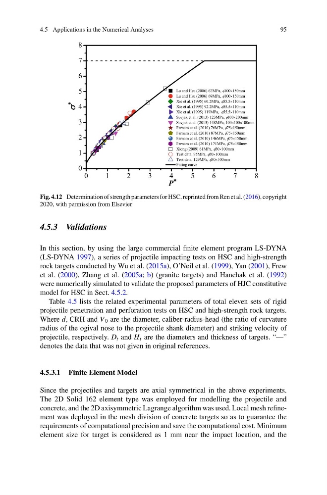
Fig. 4.12 Determination of strength parameters for HSC, reprinted from Ren et al. (2016), copyright
2020, with permission from Elsevier
4.5.3 Validations
In this section, by using the large commercial finite element program LS-DYNA
(LS-DYNA 1997), a series of projectile impacting tests on HSC and high-strength
rock targets conducted by Wu et al. (2015a), O’Neil et al. (1999), Yan (2001), Frew
et al. (2000), Zhang et al. (2005a; b) (granite targets) and Hanchak et al. (1992)
were numerically simulated to validate the proposed parameters of HJC constitutive
model for HSC in Sect. 4.5.2.
Table 4.5 lists the related experimental parameters of total eleven sets of rigid
projectile penetration and perforation tests on HSC and high-strength rock targets.
Where d, CRH and V 0 are the diameter, caliber-radius-head (the ratio of curvature
radius of the ogival nose to the projectile shank diameter) and striking velocity of
projectile, respectively. D t and H t are the diameters and thickness of targets. “—”
denotes the data that was not given in original references.
4.5.3.1 Finite Element Model
Since the projectiles and targets are axial symmetrical in the above experiments.
The 2D Solid 162 element type was employed for modelling the projectile and
concrete, and the 2D axisymmetric Lagrange algorithm was used. Local mesh refinement was deployed in the mesh division of concrete targets so as to guarantee the
requirements of computational precision and save the computational cost. Minimum
element size for target is considered as 1 mm near the impact location, and the
95
Fig. 4.12 Determination of strength parameters for HSC, reprinted from Ren et al. (2016), copyright
2020, with permission from Elsevier
4.5.3 Validations
In this section, by using the large commercial finite element program LS-DYNA
(LS-DYNA 1997), a series of projectile impacting tests on HSC and high-strength
rock targets conducted by Wu et al. (2015a), O’Neil et al. (1999), Yan (2001), Frew
et al. (2000), Zhang et al. (2005a; b) (granite targets) and Hanchak et al. (1992)
were numerically simulated to validate the proposed parameters of HJC constitutive
model for HSC in Sect. 4.5.2.
Table 4.5 lists the related experimental parameters of total eleven sets of rigid
projectile penetration and perforation tests on HSC and high-strength rock targets.
Where d, CRH and V 0 are the diameter, caliber-radius-head (the ratio of curvature
radius of the ogival nose to the projectile shank diameter) and striking velocity of
projectile, respectively. D t and H t are the diameters and thickness of targets. “—”
denotes the data that was not given in original references.
4.5.3.1 Finite Element Model
Since the projectiles and targets are axial symmetrical in the above experiments.
The 2D Solid 162 element type was employed for modelling the projectile and
concrete, and the 2D axisymmetric Lagrange algorithm was used. Local mesh refinement was deployed in the mesh division of concrete targets so as to guarantee the
requirements of computational precision and save the computational cost. Minimum
element size for target is considered as 1 mm near the impact location, and the