

7.4 Chaotic Dynamics of Size-Dependent Graded Timoshenko Beams
215
˜
z =
A
E (˜ z) ˜
zd A
A
E (˜ z) d A
.
(7.35)
The expression (7.35) allows one to exclude the terms with coefficients B 11
from the system of equations, which significantly simplifies the system of equations
obtained in Refs. [57, 101].
7.4.3 Derivation of the Equations of Motion
In order to derive equations of motion of the FG Timoshenko beam on a basis of the
modified couple stress theory, we substitute (7.23) in (7.29)–(7.33). As a result, the
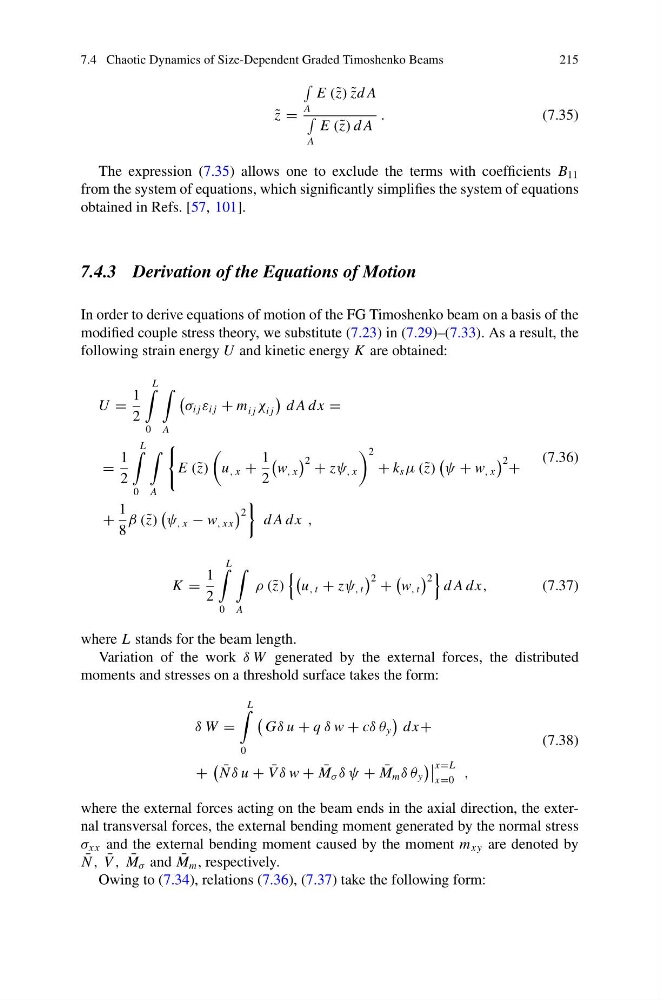
following strain energy U and kinetic energy K are obtained:
U =
1
2
L
0
A
σ i j ε i j + m i j χ i j
d A dx =
=
1
2
L
0
A
E (˜ z)
u , x +
1
2
w , x
2 + zψ , x
2
+ k s μ (˜ z)
ψ + w , x
2 +
+
1
8
β (˜ z)
ψ , x − w , xx
2
d A dx ,
(7.36)
K =
1
2
L
0
A
ρ (˜ z)
u , t + zψ , t
2 +
w , t
2
d A dx,
(7.37)
where L stands for the beam length.
Variation of the work δ W generated by the external forces, the distributed
moments and stresses on a threshold surface takes the form:
δ W =
L
0
Gδ u + q δ w + cδ θ y
dx+
+
¯
N δ u + ¯
V δ w + ¯
M σ δ ψ + ¯
M m δ θ y
x=L
x=0
,
(7.38)
where the external forces acting on the beam ends in the axial direction, the external transversal forces, the external bending moment generated by the normal stress
σ xx and the external bending moment caused by the moment m xy are denoted by
¯
N , ¯
V , ¯
M σ and ¯
M m , respectively.
Owing to (7.34), relations (7.36), (7.37) take the following form:
215
˜
z =
A
E (˜ z) ˜
zd A
A
E (˜ z) d A
.
(7.35)
The expression (7.35) allows one to exclude the terms with coefficients B 11
from the system of equations, which significantly simplifies the system of equations
obtained in Refs. [57, 101].
7.4.3 Derivation of the Equations of Motion
In order to derive equations of motion of the FG Timoshenko beam on a basis of the
modified couple stress theory, we substitute (7.23) in (7.29)–(7.33). As a result, the
following strain energy U and kinetic energy K are obtained:
U =
1
2
L
0
A
σ i j ε i j + m i j χ i j
d A dx =
=
1
2
L
0
A
E (˜ z)
u , x +
1
2
w , x
2 + zψ , x
2
+ k s μ (˜ z)
ψ + w , x
2 +
+
1
8
β (˜ z)
ψ , x − w , xx
2
d A dx ,
(7.36)
K =
1
2
L
0
A
ρ (˜ z)
u , t + zψ , t
2 +
w , t
2
d A dx,
(7.37)
where L stands for the beam length.
Variation of the work δ W generated by the external forces, the distributed
moments and stresses on a threshold surface takes the form:
δ W =
L
0
Gδ u + q δ w + cδ θ y
dx+
+
¯
N δ u + ¯
V δ w + ¯
M σ δ ψ + ¯
M m δ θ y
x=L
x=0
,
(7.38)
where the external forces acting on the beam ends in the axial direction, the external transversal forces, the external bending moment generated by the normal stress
σ xx and the external bending moment caused by the moment m xy are denoted by
¯
N , ¯
V , ¯
M σ and ¯
M m , respectively.
Owing to (7.34), relations (7.36), (7.37) take the following form: