

50
N. K. Jha et al.
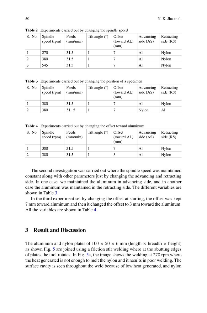
Table 2 Experiments carried out by changing the spindle speed
S. No. Spindle
speed (rpm)
Feeds
(mm/min)
Tilt angle (°) Offset
(toward AL)
(mm)
Advancing
side (AS)
Retracting
side (RS)
1
270
31.5
1
7
Al
Nylon
2
380
31.5
1
7
Al
Nylon
3
545
31.5
1
7
Al
Nylon
Table 3 Experiments carried out by changing the position of a specimen
S. No. Spindle
speed (rpm)
Feeds
(mm/min)
Tilt angle (°) Offset
(toward AL)
(mm)
Advancing
side (AS)
Retracting
side (RS)
1
380
31.5
1
7
Al
Nylon
2
380
31. 5
1
7
Nylon
Al
Table 4 Experiments carried out by changing the offset toward aluminum
S. No. Spindle
speed (rpm)
Feeds
(mm/min)
Tilt angle (°) Offset
(toward AL)
(mm)
Advancing
side (AS)
Retracting
side (RS)
1
380
31.5
1
7
Al
Nylon
2
380
31.5
1
3
Al
Nylon
The second investigation was carried out where the spindle speed was maintained
constant along with other parameters just by changing the advancing and retracting
side. In one case, we maintained the aluminum in advancing side, and in another
case the aluminum was maintained in the retracting side. The different variables are
shown in Table 3.
In the third experiment set by changing the offset at starting, the offset was kept
7 mm toward aluminum and then it changed the offset to 3 mm toward the aluminum.
All the variables are shown in Table 4.
3 Result and Discussion
The aluminum and nylon plates of 100 × 50 × 6 mm (length × breadth × height)
as shown Fig. 5 are joined using a friction stir welding where at the abutting edges
of plates the tool rotates. In Fig. 5a, the image shows the welding at 270 rpm where
the heat generated is not enough to melt the nylon and it results in poor welding. The
surface cavity is seen throughout the weld because of low heat generated, and nylon
N. K. Jha et al.
Table 2 Experiments carried out by changing the spindle speed
S. No. Spindle
speed (rpm)
Feeds
(mm/min)
Tilt angle (°) Offset
(toward AL)
(mm)
Advancing
side (AS)
Retracting
side (RS)
1
270
31.5
1
7
Al
Nylon
2
380
31.5
1
7
Al
Nylon
3
545
31.5
1
7
Al
Nylon
Table 3 Experiments carried out by changing the position of a specimen
S. No. Spindle
speed (rpm)
Feeds
(mm/min)
Tilt angle (°) Offset
(toward AL)
(mm)
Advancing
side (AS)
Retracting
side (RS)
1
380
31.5
1
7
Al
Nylon
2
380
31. 5
1
7
Nylon
Al
Table 4 Experiments carried out by changing the offset toward aluminum
S. No. Spindle
speed (rpm)
Feeds
(mm/min)
Tilt angle (°) Offset
(toward AL)
(mm)
Advancing
side (AS)
Retracting
side (RS)
1
380
31.5
1
7
Al
Nylon
2
380
31.5
1
3
Al
Nylon
The second investigation was carried out where the spindle speed was maintained
constant along with other parameters just by changing the advancing and retracting
side. In one case, we maintained the aluminum in advancing side, and in another
case the aluminum was maintained in the retracting side. The different variables are
shown in Table 3.
In the third experiment set by changing the offset at starting, the offset was kept
7 mm toward aluminum and then it changed the offset to 3 mm toward the aluminum.
All the variables are shown in Table 4.
3 Result and Discussion
The aluminum and nylon plates of 100 × 50 × 6 mm (length × breadth × height)
as shown Fig. 5 are joined using a friction stir welding where at the abutting edges
of plates the tool rotates. In Fig. 5a, the image shows the welding at 270 rpm where
the heat generated is not enough to melt the nylon and it results in poor welding. The
surface cavity is seen throughout the weld because of low heat generated, and nylon