

474
A. Talli and A. C. Giriyapur
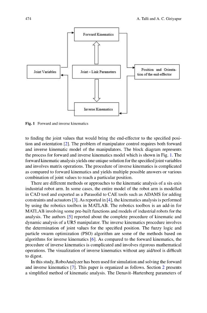
Fig. 1 Forward and inverse kinematics
to finding the joint values that would bring the end-effector to the specified position and orientation [2]. The problem of manipulator control requires both forward
and inverse kinematic model of the manipulators. The block diagram represents
the process for forward and inverse kinematics model which is shown in Fig. 1. The
forward kinematic analysis yields one unique solution for the specified joint variables
and involves matrix operations. The procedure of inverse kinematics is complicated
as compared to forward kinematics and yields multiple possible answers or various
combination of joint values to reach a particular position.
There are different methods or approaches to the kinematic analysis of a six-axis
industrial robot arm. In some cases, the entire model of the robot arm is modelled
in CAD tool and exported as a Parasolid to CAE tools such as ADAMS for adding
constraints and actuators [3]. As reported in [4], the kinematics analysis is performed
by using the robotics toolbox in MATLAB. The robotics toolbox is an add-in for
MATLAB involving some pre-built functions and models of industrial robots for the
analysis. The authors [5] reported about the complete procedure of kinematic and
dynamic analysis of a UR5 manipulator. The inverse kinematics procedure involves
the determination of joint values for the specified position. The fuzzy logic and
particle swarm optimization (PSO) algorithm are some of the methods based on
algorithms for inverse kinematics [6]. As compared to the forward kinematics, the
procedure of inverse kinematics is complicated and involves rigorous mathematical
operations. The visualization of inverse kinematics without any aid/tool is difficult
to digest.
In this study, RoboAnalyzer has been used for simulation and solving the forward
and inverse kinematics [7]. This paper is organized as follows. Section 2 presents
a simplified method of kinematic analysis. The Denavit–Hartenberg parameters of
A. Talli and A. C. Giriyapur
Fig. 1 Forward and inverse kinematics
to finding the joint values that would bring the end-effector to the specified position and orientation [2]. The problem of manipulator control requires both forward
and inverse kinematic model of the manipulators. The block diagram represents
the process for forward and inverse kinematics model which is shown in Fig. 1. The
forward kinematic analysis yields one unique solution for the specified joint variables
and involves matrix operations. The procedure of inverse kinematics is complicated
as compared to forward kinematics and yields multiple possible answers or various
combination of joint values to reach a particular position.
There are different methods or approaches to the kinematic analysis of a six-axis
industrial robot arm. In some cases, the entire model of the robot arm is modelled
in CAD tool and exported as a Parasolid to CAE tools such as ADAMS for adding
constraints and actuators [3]. As reported in [4], the kinematics analysis is performed
by using the robotics toolbox in MATLAB. The robotics toolbox is an add-in for
MATLAB involving some pre-built functions and models of industrial robots for the
analysis. The authors [5] reported about the complete procedure of kinematic and
dynamic analysis of a UR5 manipulator. The inverse kinematics procedure involves
the determination of joint values for the specified position. The fuzzy logic and
particle swarm optimization (PSO) algorithm are some of the methods based on
algorithms for inverse kinematics [6]. As compared to the forward kinematics, the
procedure of inverse kinematics is complicated and involves rigorous mathematical
operations. The visualization of inverse kinematics without any aid/tool is difficult
to digest.
In this study, RoboAnalyzer has been used for simulation and solving the forward
and inverse kinematics [7]. This paper is organized as follows. Section 2 presents
a simplified method of kinematic analysis. The Denavit–Hartenberg parameters of