

Kinematic Analysis of Planar Mechanisms …
383
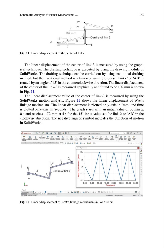
Fig. 11 Linear displacement of the center of link-3
The linear displacement of the center of link-3 is measured by using the graphical technique. The drafting technique is executed by using the drawing module of
SolidWorks. The drafting technique can be carried out by using traditional drafting
method, but the traditional method is a time-consuming process. Link-2 or ‘AB’ is
rotated by an angle of 15° in the counterclockwise direction. The linear displacement
of the center of the link-3 is measured graphically and found to be 102 mm is shown
in Fig. 11.
The linear displacement value of the center of link-3 is measured by using the
SolidWorks motion analysis. Figure 12 shows the linear displacement of Watt’s
linkage mechanism. The linear displacement is plotted on y-axis in ‘mm’ and time
is plotted on x-axis in ‘seconds.’ The graph starts with an initial value of 30 mm at
0 s and reaches −72 mm at 5 s for the 15° input value set for link-2 or ‘AB’ in the
clockwise direction. The negative sign or symbol indicates the direction of motion
in SolidWorks.
Fig. 12 Linear displacement of Watt’s linkage mechanism in SolidWorks
383
Fig. 11 Linear displacement of the center of link-3
The linear displacement of the center of link-3 is measured by using the graphical technique. The drafting technique is executed by using the drawing module of
SolidWorks. The drafting technique can be carried out by using traditional drafting
method, but the traditional method is a time-consuming process. Link-2 or ‘AB’ is
rotated by an angle of 15° in the counterclockwise direction. The linear displacement
of the center of the link-3 is measured graphically and found to be 102 mm is shown
in Fig. 11.
The linear displacement value of the center of link-3 is measured by using the
SolidWorks motion analysis. Figure 12 shows the linear displacement of Watt’s
linkage mechanism. The linear displacement is plotted on y-axis in ‘mm’ and time
is plotted on x-axis in ‘seconds.’ The graph starts with an initial value of 30 mm at
0 s and reaches −72 mm at 5 s for the 15° input value set for link-2 or ‘AB’ in the
clockwise direction. The negative sign or symbol indicates the direction of motion
in SolidWorks.
Fig. 12 Linear displacement of Watt’s linkage mechanism in SolidWorks