

Kinematic Analysis of Planar Mechanisms …
381
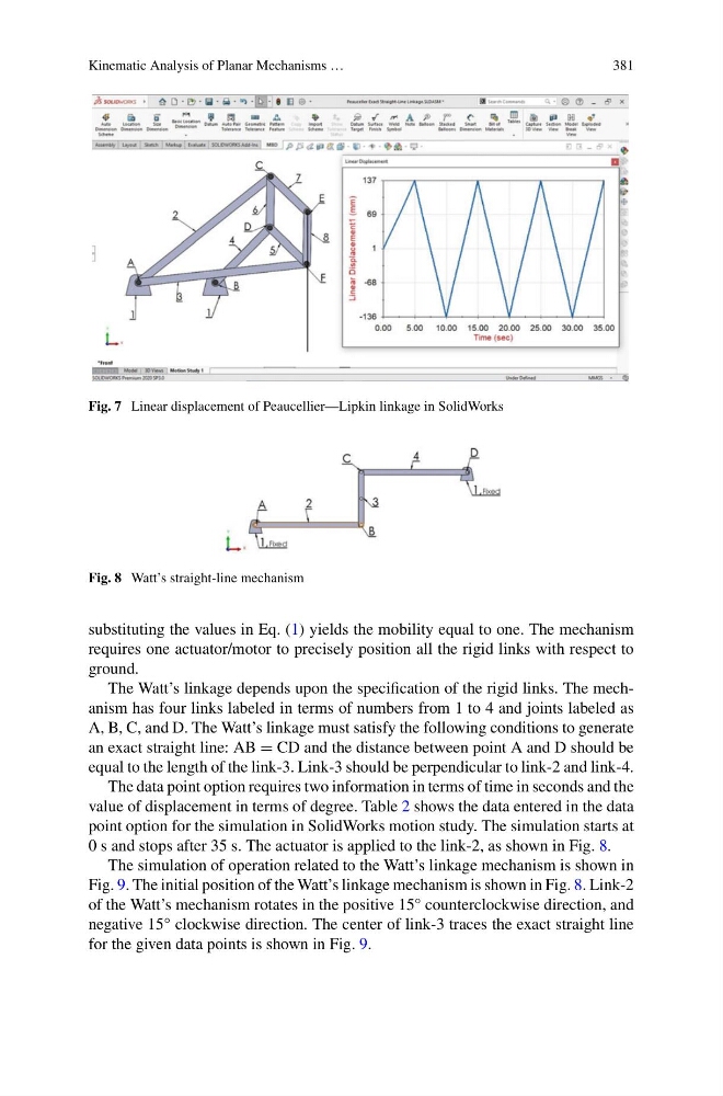
Fig. 7 Linear displacement of Peaucellier—Lipkin linkage in SolidWorks
Fig. 8 Watt’s straight-line mechanism
substituting the values in Eq. (1) yields the mobility equal to one. The mechanism
requires one actuator/motor to precisely position all the rigid links with respect to
ground.
The Watt’s linkage depends upon the specification of the rigid links. The mechanism has four links labeled in terms of numbers from 1 to 4 and joints labeled as
A, B, C, and D. The Watt’s linkage must satisfy the following conditions to generate
an exact straight line: AB = CD and the distance between point A and D should be
equal to the length of the link-3. Link-3 should be perpendicular to link-2 and link-4.
The data point option requires two information in terms of time in seconds and the
value of displacement in terms of degree. Table 2 shows the data entered in the data
point option for the simulation in SolidWorks motion study. The simulation starts at
0 s and stops after 35 s. The actuator is applied to the link-2, as shown in Fig. 8.
The simulation of operation related to the Watt’s linkage mechanism is shown in
Fig. 9. The initial position of the Watt’s linkage mechanism is shown in Fig. 8. Link-2
of the Watt’s mechanism rotates in the positive 15° counterclockwise direction, and
negative 15° clockwise direction. The center of link-3 traces the exact straight line
for the given data points is shown in Fig. 9.
381
Fig. 7 Linear displacement of Peaucellier—Lipkin linkage in SolidWorks
Fig. 8 Watt’s straight-line mechanism
substituting the values in Eq. (1) yields the mobility equal to one. The mechanism
requires one actuator/motor to precisely position all the rigid links with respect to
ground.
The Watt’s linkage depends upon the specification of the rigid links. The mechanism has four links labeled in terms of numbers from 1 to 4 and joints labeled as
A, B, C, and D. The Watt’s linkage must satisfy the following conditions to generate
an exact straight line: AB = CD and the distance between point A and D should be
equal to the length of the link-3. Link-3 should be perpendicular to link-2 and link-4.
The data point option requires two information in terms of time in seconds and the
value of displacement in terms of degree. Table 2 shows the data entered in the data
point option for the simulation in SolidWorks motion study. The simulation starts at
0 s and stops after 35 s. The actuator is applied to the link-2, as shown in Fig. 8.
The simulation of operation related to the Watt’s linkage mechanism is shown in
Fig. 9. The initial position of the Watt’s linkage mechanism is shown in Fig. 8. Link-2
of the Watt’s mechanism rotates in the positive 15° counterclockwise direction, and
negative 15° clockwise direction. The center of link-3 traces the exact straight line
for the given data points is shown in Fig. 9.