

Kinematic Analysis of Planar Mechanisms …
377
SolidWorks. The first type of motion simulation is known as animation; it is the basic
and primary level of simulation and does not provide any results. The second level
is known as the basic motion, and third level is known as motion analysis. The third
level of motion study is used for simulation and plotting the results. Figure 1 shows
various options available in the motion analysis, such as actuator, results, time-line,
force, spring, gravity, and solid contact. The motion study option is only activated in
the assembly module of SolidWorks [7].
2.1 Workflow
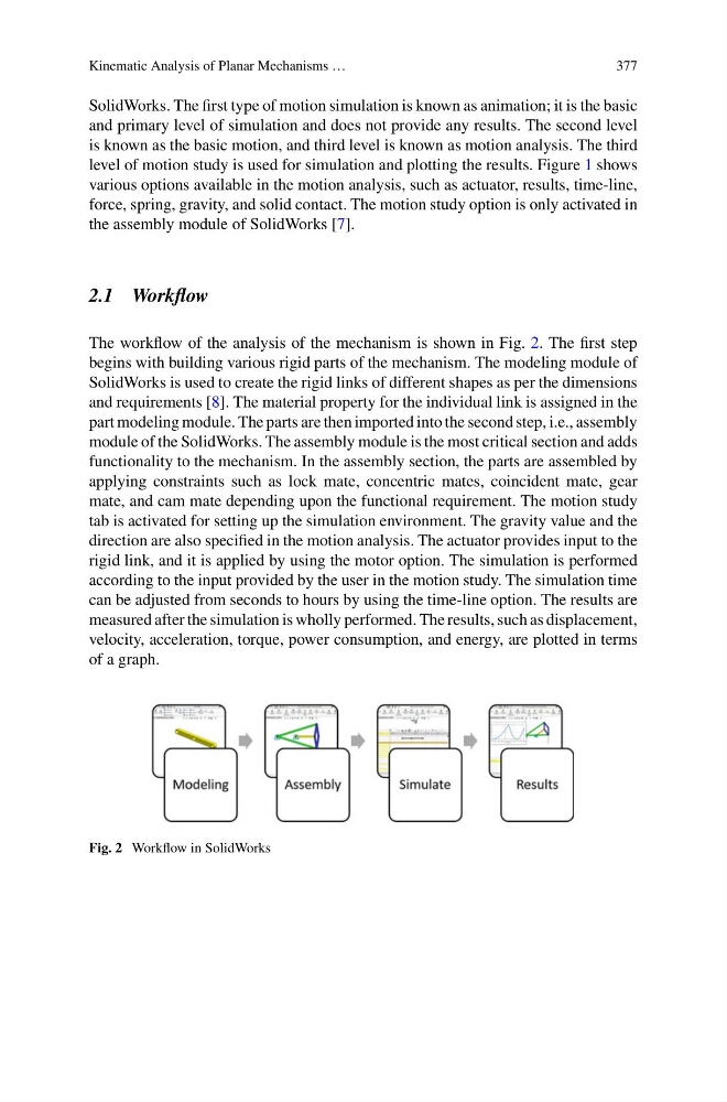
The workflow of the analysis of the mechanism is shown in Fig. 2. The first step
begins with building various rigid parts of the mechanism. The modeling module of
SolidWorks is used to create the rigid links of different shapes as per the dimensions
and requirements [8]. The material property for the individual link is assigned in the
part modeling module. The parts are then imported into the second step, i.e., assembly
module of the SolidWorks. The assembly module is the most critical section and adds
functionality to the mechanism. In the assembly section, the parts are assembled by
applying constraints such as lock mate, concentric mates, coincident mate, gear
mate, and cam mate depending upon the functional requirement. The motion study
tab is activated for setting up the simulation environment. The gravity value and the
direction are also specified in the motion analysis. The actuator provides input to the
rigid link, and it is applied by using the motor option. The simulation is performed
according to the input provided by the user in the motion study. The simulation time
can be adjusted from seconds to hours by using the time-line option. The results are
measured after the simulation is wholly performed. The results, such as displacement,
velocity, acceleration, torque, power consumption, and energy, are plotted in terms
of a graph.
Fig. 2 Workflow in SolidWorks
377
SolidWorks. The first type of motion simulation is known as animation; it is the basic
and primary level of simulation and does not provide any results. The second level
is known as the basic motion, and third level is known as motion analysis. The third
level of motion study is used for simulation and plotting the results. Figure 1 shows
various options available in the motion analysis, such as actuator, results, time-line,
force, spring, gravity, and solid contact. The motion study option is only activated in
the assembly module of SolidWorks [7].
2.1 Workflow
The workflow of the analysis of the mechanism is shown in Fig. 2. The first step
begins with building various rigid parts of the mechanism. The modeling module of
SolidWorks is used to create the rigid links of different shapes as per the dimensions
and requirements [8]. The material property for the individual link is assigned in the
part modeling module. The parts are then imported into the second step, i.e., assembly
module of the SolidWorks. The assembly module is the most critical section and adds
functionality to the mechanism. In the assembly section, the parts are assembled by
applying constraints such as lock mate, concentric mates, coincident mate, gear
mate, and cam mate depending upon the functional requirement. The motion study
tab is activated for setting up the simulation environment. The gravity value and the
direction are also specified in the motion analysis. The actuator provides input to the
rigid link, and it is applied by using the motor option. The simulation is performed
according to the input provided by the user in the motion study. The simulation time
can be adjusted from seconds to hours by using the time-line option. The results are
measured after the simulation is wholly performed. The results, such as displacement,
velocity, acceleration, torque, power consumption, and energy, are plotted in terms
of a graph.
Fig. 2 Workflow in SolidWorks