

Experimental Measurement of Laminar Flame Velocities of LPG–Air …
299
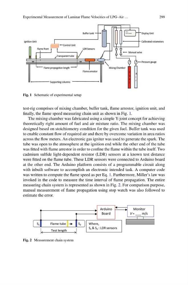
Fig. 1 Schematic of experimental setup
test-rig comprises of mixing chamber, buffer tank, flame arrestor, ignition unit, and
finally, the flame speed measuring chain unit as shown in Fig. 1.
The mixing chamber was fabricated using a simple Y-joint concept for achieving
theoretically right amount of fuel and air mixture ratio. The mixing chamber was
designed based on stoichiometry condition for the given fuel. Buffer tank was used
to enable constant flow of required air and there by overcome variation in area ratios
across the flow meters. An electronic gas igniter was used to generate the spark. The
tube was open to the atmosphere at the ignition end while the other end of the tube
was fitted with flame arrestor in order to confine the flame within the tube itself. Two
cadmium sulfide light-dependent resistor (LDR) sensors at a known test distance
were fitted on the flame tube. These LDR sensors were connected to Arduino board
at the other end. The Arduino platform consists of a programmable circuit along
with inbuilt software to accomplish an electronic intended task. A computer code
was written to compute the flame speed as per Eq. 1. Furthermore, Miller’s law was
invoked in the code to measure the time interval of flame propagation. The entire
measuring chain system is represented as shown in Fig. 2. For comparison purpose,
manual measurement of flame propagation using stop watch was also followed to
estimate the error.
Fig. 2 Measurement chain system
299
Fig. 1 Schematic of experimental setup
test-rig comprises of mixing chamber, buffer tank, flame arrestor, ignition unit, and
finally, the flame speed measuring chain unit as shown in Fig. 1.
The mixing chamber was fabricated using a simple Y-joint concept for achieving
theoretically right amount of fuel and air mixture ratio. The mixing chamber was
designed based on stoichiometry condition for the given fuel. Buffer tank was used
to enable constant flow of required air and there by overcome variation in area ratios
across the flow meters. An electronic gas igniter was used to generate the spark. The
tube was open to the atmosphere at the ignition end while the other end of the tube
was fitted with flame arrestor in order to confine the flame within the tube itself. Two
cadmium sulfide light-dependent resistor (LDR) sensors at a known test distance
were fitted on the flame tube. These LDR sensors were connected to Arduino board
at the other end. The Arduino platform consists of a programmable circuit along
with inbuilt software to accomplish an electronic intended task. A computer code
was written to compute the flame speed as per Eq. 1. Furthermore, Miller’s law was
invoked in the code to measure the time interval of flame propagation. The entire
measuring chain system is represented as shown in Fig. 2. For comparison purpose,
manual measurement of flame propagation using stop watch was also followed to
estimate the error.
Fig. 2 Measurement chain system