

248
K. Mekrisuh et al.
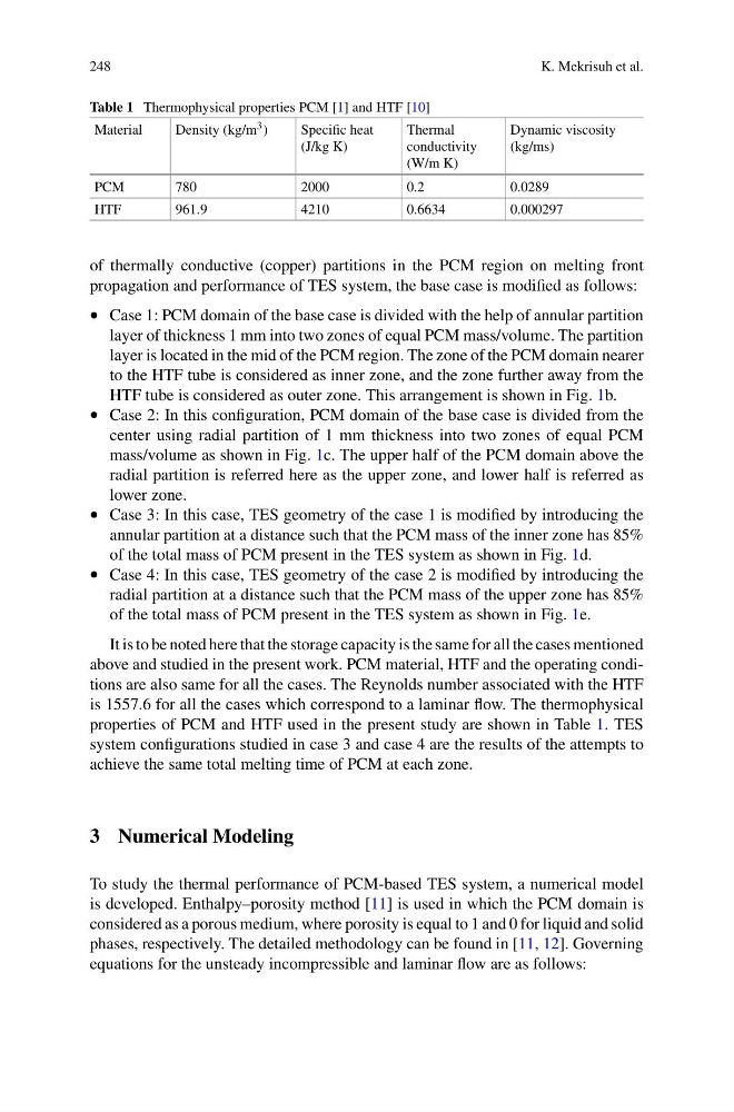
Table 1 Thermophysical properties PCM [1] and HTF [10]
Material
Density (kg/m 3 )
Specific heat
(J/kg K)
Thermal
conductivity
(W/m K)
Dynamic viscosity
(kg/ms)
PCM
780
2000
0.2
0.0289
HTF
961.9
4210
0.6634
0.000297
of thermally conductive (copper) partitions in the PCM region on melting front
propagation and performance of TES system, the base case is modified as follows:
• Case 1: PCM domain of the base case is divided with the help of annular partition
layer of thickness 1 mm into two zones of equal PCM mass/volume. The partition
layer is located in the mid of the PCM region. The zone of the PCM domain nearer
to the HTF tube is considered as inner zone, and the zone further away from the
HTF tube is considered as outer zone. This arrangement is shown in Fig. 1b.
• Case 2: In this configuration, PCM domain of the base case is divided from the
center using radial partition of 1 mm thickness into two zones of equal PCM
mass/volume as shown in Fig. 1c. The upper half of the PCM domain above the
radial partition is referred here as the upper zone, and lower half is referred as
lower zone.
• Case 3: In this case, TES geometry of the case 1 is modified by introducing the
annular partition at a distance such that the PCM mass of the inner zone has 85%
of the total mass of PCM present in the TES system as shown in Fig. 1d.
• Case 4: In this case, TES geometry of the case 2 is modified by introducing the
radial partition at a distance such that the PCM mass of the upper zone has 85%
of the total mass of PCM present in the TES system as shown in Fig. 1e.
It is to be noted here that the storage capacity is the same for all the cases mentioned
above and studied in the present work. PCM material, HTF and the operating conditions are also same for all the cases. The Reynolds number associated with the HTF
is 1557.6 for all the cases which correspond to a laminar flow. The thermophysical
properties of PCM and HTF used in the present study are shown in Table 1. TES
system configurations studied in case 3 and case 4 are the results of the attempts to
achieve the same total melting time of PCM at each zone.
3 Numerical Modeling
To study the thermal performance of PCM-based TES system, a numerical model
is developed. Enthalpy–porosity method [11] is used in which the PCM domain is
considered as a porous medium, where porosity is equal to 1 and 0 for liquid and solid
phases, respectively. The detailed methodology can be found in [11, 12]. Governing
equations for the unsteady incompressible and laminar flow are as follows:
K. Mekrisuh et al.
Table 1 Thermophysical properties PCM [1] and HTF [10]
Material
Density (kg/m 3 )
Specific heat
(J/kg K)
Thermal
conductivity
(W/m K)
Dynamic viscosity
(kg/ms)
PCM
780
2000
0.2
0.0289
HTF
961.9
4210
0.6634
0.000297
of thermally conductive (copper) partitions in the PCM region on melting front
propagation and performance of TES system, the base case is modified as follows:
• Case 1: PCM domain of the base case is divided with the help of annular partition
layer of thickness 1 mm into two zones of equal PCM mass/volume. The partition
layer is located in the mid of the PCM region. The zone of the PCM domain nearer
to the HTF tube is considered as inner zone, and the zone further away from the
HTF tube is considered as outer zone. This arrangement is shown in Fig. 1b.
• Case 2: In this configuration, PCM domain of the base case is divided from the
center using radial partition of 1 mm thickness into two zones of equal PCM
mass/volume as shown in Fig. 1c. The upper half of the PCM domain above the
radial partition is referred here as the upper zone, and lower half is referred as
lower zone.
• Case 3: In this case, TES geometry of the case 1 is modified by introducing the
annular partition at a distance such that the PCM mass of the inner zone has 85%
of the total mass of PCM present in the TES system as shown in Fig. 1d.
• Case 4: In this case, TES geometry of the case 2 is modified by introducing the
radial partition at a distance such that the PCM mass of the upper zone has 85%
of the total mass of PCM present in the TES system as shown in Fig. 1e.
It is to be noted here that the storage capacity is the same for all the cases mentioned
above and studied in the present work. PCM material, HTF and the operating conditions are also same for all the cases. The Reynolds number associated with the HTF
is 1557.6 for all the cases which correspond to a laminar flow. The thermophysical
properties of PCM and HTF used in the present study are shown in Table 1. TES
system configurations studied in case 3 and case 4 are the results of the attempts to
achieve the same total melting time of PCM at each zone.
3 Numerical Modeling
To study the thermal performance of PCM-based TES system, a numerical model
is developed. Enthalpy–porosity method [11] is used in which the PCM domain is
considered as a porous medium, where porosity is equal to 1 and 0 for liquid and solid
phases, respectively. The detailed methodology can be found in [11, 12]. Governing
equations for the unsteady incompressible and laminar flow are as follows: