

Applicability of Bobbin Tool Friction Stir Welding …
229
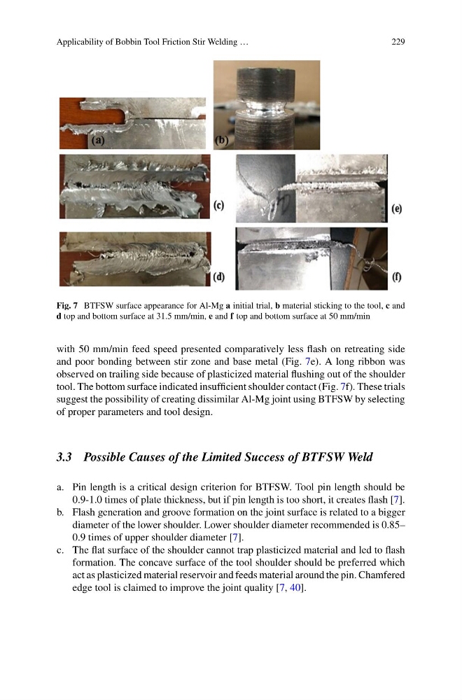
Fig. 7 BTFSW surface appearance for Al-Mg a initial trial, b material sticking to the tool, c and
d top and bottom surface at 31.5 mm/min, e and f top and bottom surface at 50 mm/min
with 50 mm/min feed speed presented comparatively less flash on retreating side
and poor bonding between stir zone and base metal (Fig. 7e). A long ribbon was
observed on trailing side because of plasticized material flushing out of the shoulder
tool. The bottom surface indicated insufficient shoulder contact (Fig. 7f). These trials
suggest the possibility of creating dissimilar Al-Mg joint using BTFSW by selecting
of proper parameters and tool design.
3.3 Possible Causes of the Limited Success of BTFSW Weld
a. Pin length is a critical design criterion for BTFSW. Tool pin length should be
0.9-1.0 times of plate thickness, but if pin length is too short, it creates flash [7].
b. Flash generation and groove formation on the joint surface is related to a bigger
diameter of the lower shoulder. Lower shoulder diameter recommended is 0.85–
0.9 times of upper shoulder diameter [7].
c. The flat surface of the shoulder cannot trap plasticized material and led to flash
formation. The concave surface of the tool shoulder should be preferred which
act as plasticized material reservoir and feeds material around the pin. Chamfered
edge tool is claimed to improve the joint quality [7, 40].
229
Fig. 7 BTFSW surface appearance for Al-Mg a initial trial, b material sticking to the tool, c and
d top and bottom surface at 31.5 mm/min, e and f top and bottom surface at 50 mm/min
with 50 mm/min feed speed presented comparatively less flash on retreating side
and poor bonding between stir zone and base metal (Fig. 7e). A long ribbon was
observed on trailing side because of plasticized material flushing out of the shoulder
tool. The bottom surface indicated insufficient shoulder contact (Fig. 7f). These trials
suggest the possibility of creating dissimilar Al-Mg joint using BTFSW by selecting
of proper parameters and tool design.
3.3 Possible Causes of the Limited Success of BTFSW Weld
a. Pin length is a critical design criterion for BTFSW. Tool pin length should be
0.9-1.0 times of plate thickness, but if pin length is too short, it creates flash [7].
b. Flash generation and groove formation on the joint surface is related to a bigger
diameter of the lower shoulder. Lower shoulder diameter recommended is 0.85–
0.9 times of upper shoulder diameter [7].
c. The flat surface of the shoulder cannot trap plasticized material and led to flash
formation. The concave surface of the tool shoulder should be preferred which
act as plasticized material reservoir and feeds material around the pin. Chamfered
edge tool is claimed to improve the joint quality [7, 40].