

damped. The pendulum part constitutes the vibration absorber. This part could be
replaced by an elastic beam, as in the experimental absorber described in Haxton
and Barr (1972), or by any other elastic component. The essential feature is that
nonlinear effects are used to suppress vibrations.
The kinetic and potential energies of the system are, respectively:
T ¼
1
2
m 1 _
x
2
þ
1
2
m 3 _
x
2
þ l
2
3
_
h
2
À 2l 3 _
x _
h sin h
þ
1
2
m 2 _
x
2
þ
1
3
l
2
2
_
h
2
À l 2 _
x _
h sin h
;
V ¼
1
2
k 1 x
2
þ
1
2
k 2 l
2
s tan
2 h:
ð4:1Þ
Using Lagrange’s equations,
d
dt
@L
@ _
x
À
@L
@x
¼ FðtÞ;
d
dt
@L
@ _
h
À
@L
@h
¼ 0; L T À V;
ð4:2Þ
the equations of motion become:
ðm 1 þ m 2 þ m 3 Þ€ x þ k 1 x À
1
2
ðm 2 l 2 þ 2m 3 l 3 Þ _
h
2 cos h þ € h sin h
¼ Q cosðXtÞ;
ð
1
3
m 2 l
2
2 þ m 3 l
2
3 Þ € h À
1
2
ðm 2 l 2 þ 2m 3 l 3 Þ€ x sin h þ k 2 l
2
s tan h 1 þ tan
2 h
À
Á ¼ 0;
ð4:3Þ
where harmonic forcing has been assumed, F(t) = Q cos (Xt). The equations can be
rearranged by eliminating h from the first equation and x from the second.
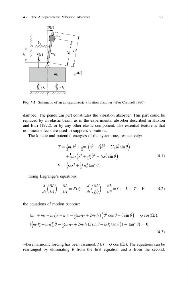
Fig. 4.1 Schematic of an autoparametric vibration absorber (after Cartmell 1990)
4.2 The Autoparametric Vibration Absorber
211
replaced by an elastic beam, as in the experimental absorber described in Haxton
and Barr (1972), or by any other elastic component. The essential feature is that
nonlinear effects are used to suppress vibrations.
The kinetic and potential energies of the system are, respectively:
T ¼
1
2
m 1 _
x
2
þ
1
2
m 3 _
x
2
þ l
2
3
_
h
2
À 2l 3 _
x _
h sin h
þ
1
2
m 2 _
x
2
þ
1
3
l
2
2
_
h
2
À l 2 _
x _
h sin h
;
V ¼
1
2
k 1 x
2
þ
1
2
k 2 l
2
s tan
2 h:
ð4:1Þ
Using Lagrange’s equations,
d
dt
@L
@ _
x
À
@L
@x
¼ FðtÞ;
d
dt
@L
@ _
h
À
@L
@h
¼ 0; L T À V;
ð4:2Þ
the equations of motion become:
ðm 1 þ m 2 þ m 3 Þ€ x þ k 1 x À
1
2
ðm 2 l 2 þ 2m 3 l 3 Þ _
h
2 cos h þ € h sin h
¼ Q cosðXtÞ;
ð
1
3
m 2 l
2
2 þ m 3 l
2
3 Þ € h À
1
2
ðm 2 l 2 þ 2m 3 l 3 Þ€ x sin h þ k 2 l
2
s tan h 1 þ tan
2 h
À
Á ¼ 0;
ð4:3Þ
where harmonic forcing has been assumed, F(t) = Q cos (Xt). The equations can be
rearranged by eliminating h from the first equation and x from the second.
Fig. 4.1 Schematic of an autoparametric vibration absorber (after Cartmell 1990)
4.2 The Autoparametric Vibration Absorber
211