

subjected to linear boundary conditions at the clamped end. Nonlinear boundary
conditions apply to the end, which is alternately free and restricted.
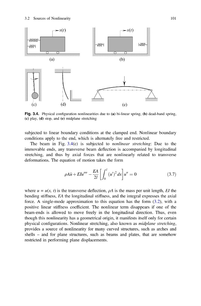
The beam in Fig. 3.4(e) is subjected to nonlinear stretching: Due to the
immovable ends, any transverse beam deflection is accompanied by longitudinal
stretching, and thus by axial forces that are nonlinearly related to transverse
deformations. The equation of motion takes the form
qA€ u þ EIu
0000
À
EA
2l
Z l
0
ðu
0
Þ
2 dx
!
u
00
¼ 0
ð3:7Þ
where u = u(x, t) is the transverse deflection, qA is the mass per unit length, EI the
bending stiffness, EA the longitudinal stiffness, and the integral expresses the axial
force. A single-mode approximation to this equation has the form (3.2), with a
positive linear stiffness coefficient. The nonlinear term disappears if one of the
beam-ends is allowed to move freely in the longitudinal direction. Thus, even
though this nonlinearity has a geometrical origin, it manifests itself only for certain
physical configurations. Nonlinear stretching, also known as midplane stretching,
provides a source of nonlinearity for many curved structures, such as arches and
shells – and for plane structures, such as beams and plates, that are somehow
restricted in performing plane displacements.
Fig. 3.4. Physical configuration nonlinearities due to (a) bi-linear spring, (b) dead-band spring,
(c) play, (d) stop, and (e) midplane stretching
3.2 Sources of Nonlinearity
101
conditions apply to the end, which is alternately free and restricted.
The beam in Fig. 3.4(e) is subjected to nonlinear stretching: Due to the
immovable ends, any transverse beam deflection is accompanied by longitudinal
stretching, and thus by axial forces that are nonlinearly related to transverse
deformations. The equation of motion takes the form
qA€ u þ EIu
0000
À
EA
2l
Z l
0
ðu
0
Þ
2 dx
!
u
00
¼ 0
ð3:7Þ
where u = u(x, t) is the transverse deflection, qA is the mass per unit length, EI the
bending stiffness, EA the longitudinal stiffness, and the integral expresses the axial
force. A single-mode approximation to this equation has the form (3.2), with a
positive linear stiffness coefficient. The nonlinear term disappears if one of the
beam-ends is allowed to move freely in the longitudinal direction. Thus, even
though this nonlinearity has a geometrical origin, it manifests itself only for certain
physical configurations. Nonlinear stretching, also known as midplane stretching,
provides a source of nonlinearity for many curved structures, such as arches and
shells – and for plane structures, such as beams and plates, that are somehow
restricted in performing plane displacements.
Fig. 3.4. Physical configuration nonlinearities due to (a) bi-linear spring, (b) dead-band spring,
(c) play, (d) stop, and (e) midplane stretching
3.2 Sources of Nonlinearity
101