

96
methods need to be independently verified. Multiple diagonal cracks growing in a wider area of the specimen are believed to
cause the increment in tensile strength which are not present in the small area of SHTB samples. In this study, an experimental methodology is presented to study the high rate behavior of resin and composites to develop a numerical model to simulate the ballistic impact damage of composite panels manufactured using Automated Tape Placement (ATP) methods. A
growing trend in composite fabrication is replacing traditional woven reinforcements and hand-layup processes with unidirectional (UD) tapes that can be cut and placed precisely in automated tape laying processes. The current practice required
for the development and certification of new composite structures follows a building block approach starting from simple
(generic) coupons, for basic material characterization, and moving to more complex structural details. One approach for
reducing development time and cost of composite structures is to increase the use of modeling and simulation at all levels of
the product development cycle. A complete constitutive model of composite material that can predict the mechanical performance and the development of damage leading to failure is still an on-going research endeavor. An essential step in the
development of constitutive model is dynamic mechanical characterization including tensile, shear, and compressive loading
using various testing techniques such as servo-hydraulic system, high rate servo-hydraulic machine, and Split Hopkinson
Pressure Bar (SHPB) to properly satisfy critical design requirements. Reliable data on the dynamic properties of these new
generation of UD tape composite materials are sparse. In this chapter, a comprehensive approach combining micromechanical modeling, dynamic mechanical characterization, and macroscale Finite Element modeling is presented to study the high
velocity impact response of carbon fiber reinforced composites manufactured from UD tapes.
17.2 Experimental Setup
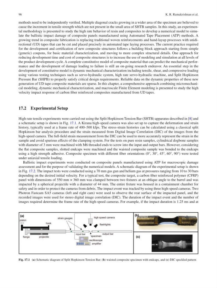
High rate tensile experiments were carried out using the Split Hopkinson Tension Bar (SHTB) apparatus described in [8] and
a schematic setup is shown in Fig. 17.1. A Kirana high- speed camera was also set up to capture the deformation and strain
history, typically used at a frame rate of 400–500 kfps. The stress-strain histories can be calculated using a classical split
Hopkinson bar analysis procedure and the strain measured from Digital Image Correlation (DIC) of the images from the
high-speed camera. The full-field strain measurement from the DIC can be used to more accurately represent the strain in the
sample and avoid spurious effects of the clamping system. For the tests on pure resin samples, cylindrical dogbone samples
with diameter of 3 mm were machined with M6 threaded ends to screw into the input and output bars. However, considering
the flat composite samples, slotted endcaps were machined and the waisted composite sample was bonded to the endcaps
using a high strength adhesive. Composite specimen with different fiber orientations (0°, 30°, 45°, 60°, 90°) were tested
under uniaxial tensile loading.
Ballistic impact experiments were conducted on composite panels manufactured using ATP for macroscopic damage
assessment and for the purpose of validating the numerical models. A schematic diagram of the experimental setup is shown
in Fig. 17.2. The impact tests were conducted using a 70 mm gas gun and helium gas at pressures ranging from 10 to 30 bars
depending on the desired initial velocity. For a typical test, the composite target, a carbon fiber reinforced polymer (CFRP)
panel with dimensions of 550 mm × 360 mm was clamped between two fixtures at an oblique angle to the barrel and was
impacted by a spherical projectile with a diameter of 44 mm. The entire fixture was housed in a containment chamber for
safety and in order to protect the cameras from debris. The impact event was tracked by using three high-speed cameras. Two
Photron Fastcam SA5 cameras (left and right cam) were used to observe the rear surface of the impacted panel, and the
recorded images were used for stereo digital image correlation (DIC). The duration of the impact event and the number of
images required determine the frame rate of the high-speed cameras. For example, if the impact duration is 1.25 ms and at
Fig. 17.1 (a) Schematic diagram of Split Hopkinson Tension Bar; (b) waisted composite specimen with endcaps, and (c) DIC speckled pattern
K. R. Ramakrishnan et al.
methods need to be independently verified. Multiple diagonal cracks growing in a wider area of the specimen are believed to
cause the increment in tensile strength which are not present in the small area of SHTB samples. In this study, an experimental methodology is presented to study the high rate behavior of resin and composites to develop a numerical model to simulate the ballistic impact damage of composite panels manufactured using Automated Tape Placement (ATP) methods. A
growing trend in composite fabrication is replacing traditional woven reinforcements and hand-layup processes with unidirectional (UD) tapes that can be cut and placed precisely in automated tape laying processes. The current practice required
for the development and certification of new composite structures follows a building block approach starting from simple
(generic) coupons, for basic material characterization, and moving to more complex structural details. One approach for
reducing development time and cost of composite structures is to increase the use of modeling and simulation at all levels of
the product development cycle. A complete constitutive model of composite material that can predict the mechanical performance and the development of damage leading to failure is still an on-going research endeavor. An essential step in the
development of constitutive model is dynamic mechanical characterization including tensile, shear, and compressive loading
using various testing techniques such as servo-hydraulic system, high rate servo-hydraulic machine, and Split Hopkinson
Pressure Bar (SHPB) to properly satisfy critical design requirements. Reliable data on the dynamic properties of these new
generation of UD tape composite materials are sparse. In this chapter, a comprehensive approach combining micromechanical modeling, dynamic mechanical characterization, and macroscale Finite Element modeling is presented to study the high
velocity impact response of carbon fiber reinforced composites manufactured from UD tapes.
17.2 Experimental Setup
High rate tensile experiments were carried out using the Split Hopkinson Tension Bar (SHTB) apparatus described in [8] and
a schematic setup is shown in Fig. 17.1. A Kirana high- speed camera was also set up to capture the deformation and strain
history, typically used at a frame rate of 400–500 kfps. The stress-strain histories can be calculated using a classical split
Hopkinson bar analysis procedure and the strain measured from Digital Image Correlation (DIC) of the images from the
high-speed camera. The full-field strain measurement from the DIC can be used to more accurately represent the strain in the
sample and avoid spurious effects of the clamping system. For the tests on pure resin samples, cylindrical dogbone samples
with diameter of 3 mm were machined with M6 threaded ends to screw into the input and output bars. However, considering
the flat composite samples, slotted endcaps were machined and the waisted composite sample was bonded to the endcaps
using a high strength adhesive. Composite specimen with different fiber orientations (0°, 30°, 45°, 60°, 90°) were tested
under uniaxial tensile loading.
Ballistic impact experiments were conducted on composite panels manufactured using ATP for macroscopic damage
assessment and for the purpose of validating the numerical models. A schematic diagram of the experimental setup is shown
in Fig. 17.2. The impact tests were conducted using a 70 mm gas gun and helium gas at pressures ranging from 10 to 30 bars
depending on the desired initial velocity. For a typical test, the composite target, a carbon fiber reinforced polymer (CFRP)
panel with dimensions of 550 mm × 360 mm was clamped between two fixtures at an oblique angle to the barrel and was
impacted by a spherical projectile with a diameter of 44 mm. The entire fixture was housed in a containment chamber for
safety and in order to protect the cameras from debris. The impact event was tracked by using three high-speed cameras. Two
Photron Fastcam SA5 cameras (left and right cam) were used to observe the rear surface of the impacted panel, and the
recorded images were used for stereo digital image correlation (DIC). The duration of the impact event and the number of
images required determine the frame rate of the high-speed cameras. For example, if the impact duration is 1.25 ms and at
Fig. 17.1 (a) Schematic diagram of Split Hopkinson Tension Bar; (b) waisted composite specimen with endcaps, and (c) DIC speckled pattern
K. R. Ramakrishnan et al.