

39
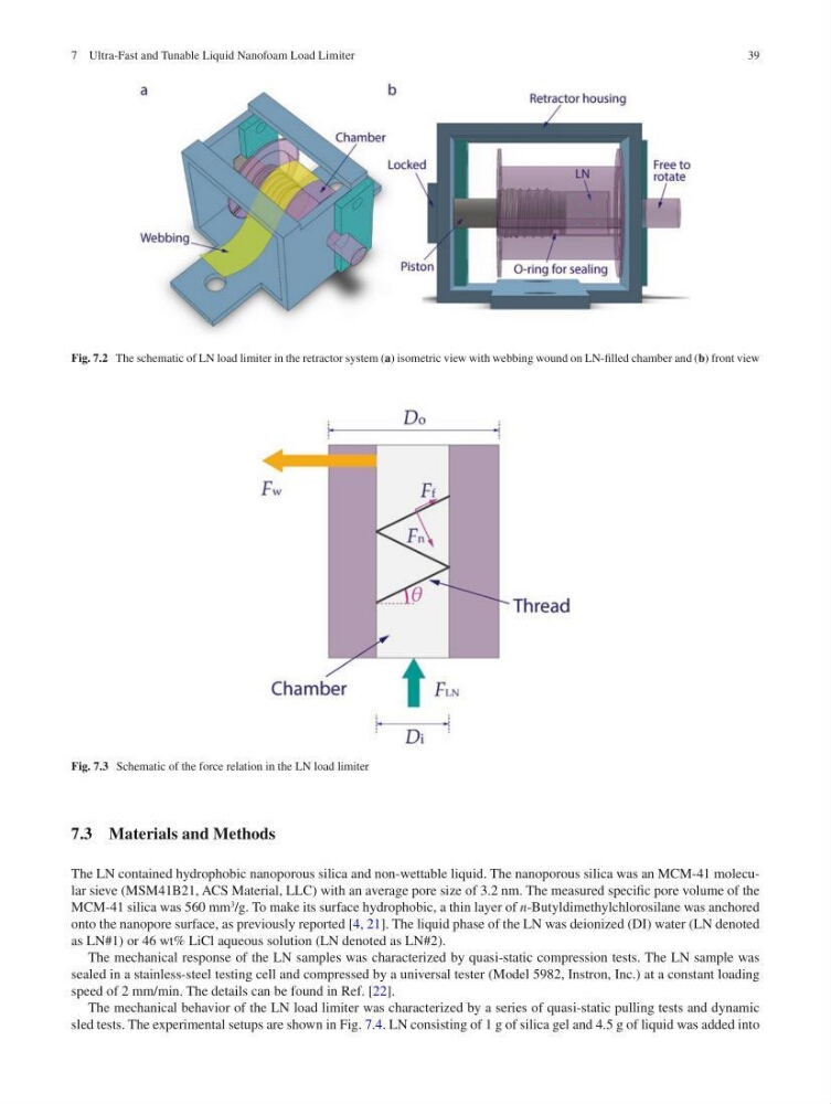
Fig. 7.2 The schematic of LN load limiter in the retractor system (a) isometric view with webbing wound on LN-filled chamber and (b) front view
Fig. 7.3 Schematic of the force relation in the LN load limiter
7.3 Materials and Methods
The LN contained hydrophobic nanoporous silica and non- wettable liquid. The nanoporous silica was an MCM-41 molecular sieve (MSM41B21, ACS Material, LLC) with an average pore size of 3.2 nm. The measured specific pore volume of the
MCM-41 silica was 560 mm
3
/g. To make its surface hydrophobic, a thin layer of n-Butyldimethylchlorosilane was anchored
onto the nanopore surface, as previously reported [4, 21]. The liquid phase of the LN was deionized (DI) water (LN denoted
as LN#1) or 46 wt% LiCl aqueous solution (LN denoted as LN#2).
The mechanical response of the LN samples was characterized by quasi-static compression tests. The LN sample was
sealed in a stainless-steel testing cell and compressed by a universal tester (Model 5982, Instron, Inc.) at a constant loading
speed of 2 mm/min. The details can be found in Ref. [22].
The mechanical behavior of the LN load limiter was characterized by a series of quasi-static pulling tests and dynamic
sled tests. The experimental setups are shown in Fig. 7.4. LN consisting of 1 g of silica gel and 4.5 g of liquid was added into
7 Ultra-Fast and Tunable Liquid Nanofoam Load Limiter
Fig. 7.2 The schematic of LN load limiter in the retractor system (a) isometric view with webbing wound on LN-filled chamber and (b) front view
Fig. 7.3 Schematic of the force relation in the LN load limiter
7.3 Materials and Methods
The LN contained hydrophobic nanoporous silica and non- wettable liquid. The nanoporous silica was an MCM-41 molecular sieve (MSM41B21, ACS Material, LLC) with an average pore size of 3.2 nm. The measured specific pore volume of the
MCM-41 silica was 560 mm
3
/g. To make its surface hydrophobic, a thin layer of n-Butyldimethylchlorosilane was anchored
onto the nanopore surface, as previously reported [4, 21]. The liquid phase of the LN was deionized (DI) water (LN denoted
as LN#1) or 46 wt% LiCl aqueous solution (LN denoted as LN#2).
The mechanical response of the LN samples was characterized by quasi-static compression tests. The LN sample was
sealed in a stainless-steel testing cell and compressed by a universal tester (Model 5982, Instron, Inc.) at a constant loading
speed of 2 mm/min. The details can be found in Ref. [22].
The mechanical behavior of the LN load limiter was characterized by a series of quasi-static pulling tests and dynamic
sled tests. The experimental setups are shown in Fig. 7.4. LN consisting of 1 g of silica gel and 4.5 g of liquid was added into
7 Ultra-Fast and Tunable Liquid Nanofoam Load Limiter