

80
5 Finite Element Formulations
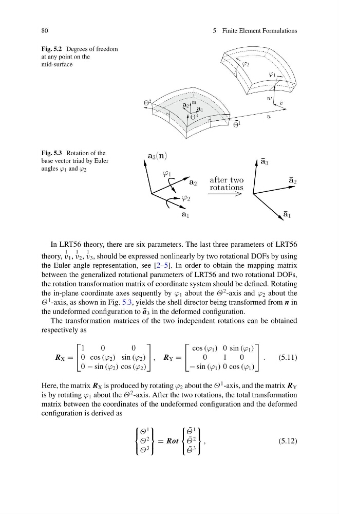
Fig. 5.2 Degrees of freedom
at any point on the
mid-surface
Θ
2
a 1
a 2
ϕ 2
Θ
3
n
Θ
1
w
u
ϕ 1
v
Fig. 5.3 Rotation of the
base vector triad by Euler
angles ϕ 1 and ϕ 2
after two
rotations
a 3 (n)
ϕ 1
a 1
¯ a 2
¯ a 3
ϕ 2
a 2
¯ a 1
In LRT56 theory, there are six parameters. The last three parameters of LRT56
theory,
1
v 1 ,
1
v 2 ,
1
v 3 , should be expressed nonlinearly by two rotational DOFs by using
the Euler angle representation, see [2–5]. In order to obtain the mapping matrix
between the generalized rotational parameters of LRT56 and two rotational DOFs,
the rotation transformation matrix of coordinate system should be defined. Rotating
the in-plane coordinate axes sequently by ϕ 1 about the Θ
2 -axis and ϕ 2 about the
Θ
1 -axis, as shown in Fig. 5.3, yields the shell director being transformed from n in
the undeformed configuration to ¯
a 3 in the deformed configuration.
The transformation matrices of the two independent rotations can be obtained
respectively as
R X =
⎡
⎣
1
0
0
0 cos (ϕ 2 ) sin (ϕ 2 )
0 − sin (ϕ 2 ) cos (ϕ 2 )
⎤
⎦ , R Y =
⎡
⎣
cos (ϕ 1 ) 0 sin (ϕ 1 )
0
1
0
− sin (ϕ 1 ) 0 cos (ϕ 1 )
⎤
⎦ .
(5.11)
Here, the matrix R X is produced by rotating ϕ 2 about the Θ
1 -axis, and the matrix R Y
is by rotating ϕ 1 about the Θ
2 -axis. After the two rotations, the total transformation
matrix between the coordinates of the undeformed configuration and the deformed
configuration is derived as
⎧
⎨
⎩
Θ
1
Θ
2
Θ
3
⎫
⎬
⎭
= Rot
⎧
⎨
⎩
¯
Θ
1
¯
Θ
2
¯
Θ
3
⎫
⎬
⎭
,
(5.12)
5 Finite Element Formulations
Fig. 5.2 Degrees of freedom
at any point on the
mid-surface
Θ
2
a 1
a 2
ϕ 2
Θ
3
n
Θ
1
w
u
ϕ 1
v
Fig. 5.3 Rotation of the
base vector triad by Euler
angles ϕ 1 and ϕ 2
after two
rotations
a 3 (n)
ϕ 1
a 1
¯ a 2
¯ a 3
ϕ 2
a 2
¯ a 1
In LRT56 theory, there are six parameters. The last three parameters of LRT56
theory,
1
v 1 ,
1
v 2 ,
1
v 3 , should be expressed nonlinearly by two rotational DOFs by using
the Euler angle representation, see [2–5]. In order to obtain the mapping matrix
between the generalized rotational parameters of LRT56 and two rotational DOFs,
the rotation transformation matrix of coordinate system should be defined. Rotating
the in-plane coordinate axes sequently by ϕ 1 about the Θ
2 -axis and ϕ 2 about the
Θ
1 -axis, as shown in Fig. 5.3, yields the shell director being transformed from n in
the undeformed configuration to ¯
a 3 in the deformed configuration.
The transformation matrices of the two independent rotations can be obtained
respectively as
R X =
⎡
⎣
1
0
0
0 cos (ϕ 2 ) sin (ϕ 2 )
0 − sin (ϕ 2 ) cos (ϕ 2 )
⎤
⎦ , R Y =
⎡
⎣
cos (ϕ 1 ) 0 sin (ϕ 1 )
0
1
0
− sin (ϕ 1 ) 0 cos (ϕ 1 )
⎤
⎦ .
(5.11)
Here, the matrix R X is produced by rotating ϕ 2 about the Θ
1 -axis, and the matrix R Y
is by rotating ϕ 1 about the Θ
2 -axis. After the two rotations, the total transformation
matrix between the coordinates of the undeformed configuration and the deformed
configuration is derived as
⎧
⎨
⎩
Θ
1
Θ
2
Θ
3
⎫
⎬
⎭
= Rot
⎧
⎨
⎩
¯
Θ
1
¯
Θ
2
¯
Θ
3
⎫
⎬
⎭
,
(5.12)