

5.1 Resultant Vectors
79
H s =
⎡
⎢
⎢
⎢
⎢
⎣
1 0 0 Θ
3 0 0 (Θ
3
)
2
0
0 00 0 0
0 1 0 0 Θ
3 0
0 (Θ
3
)
2
0 0 0 0 0
0 0 1 0 0 Θ
3
0
0 (Θ
3
)
2 0 0 0 0
0 0 0 0 0 0
0
0
0 1 0 Θ
3 0
0 0 0 0 0 0
0
0
0 0 1 0 Θ
3
⎤
⎥
⎥
⎥
⎥
⎦
.
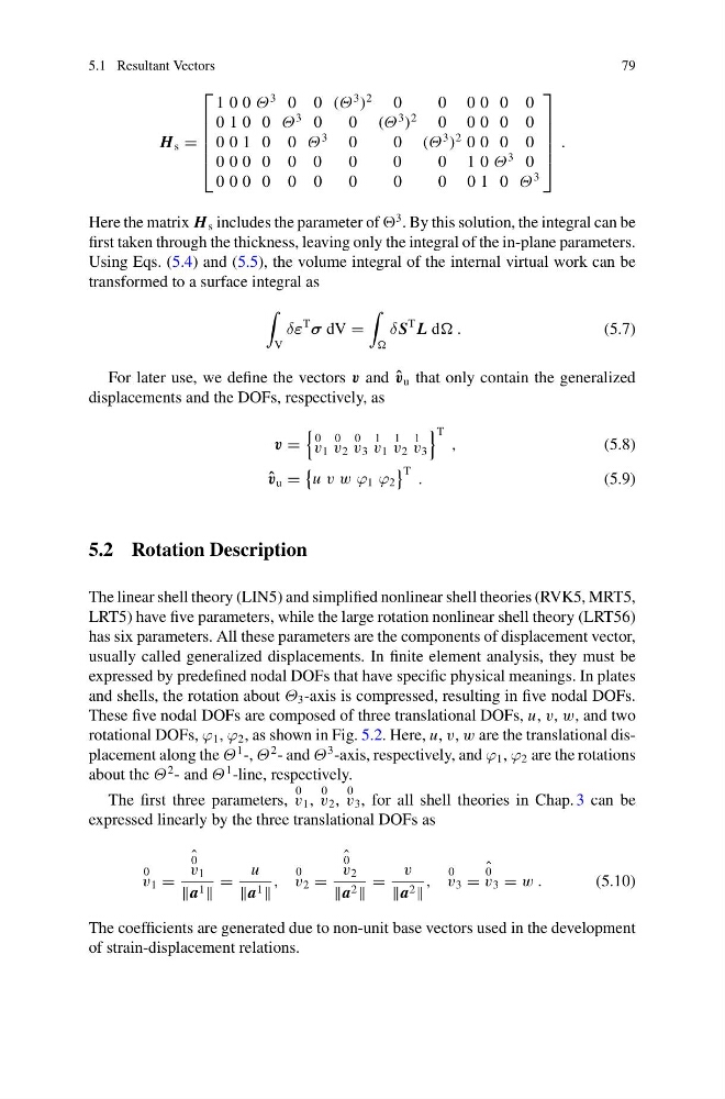
Here the matrix H s includes the parameter of
3 . By this solution, the integral can be
first taken through the thickness, leaving only the integral of the in-plane parameters.
Using Eqs. (5.4) and (5.5), the volume integral of the internal virtual work can be
transformed to a surface integral as
V
δε
T
σ dV =
δ S
T L d .
(5.7)
For later use, we define the vectors v and ˆ
v u that only contain the generalized
displacements and the DOFs, respectively, as
v =
0
v 1
0
v 2
0
v 3
1
v 1
1
v 2
1
v 3
T ,
(5.8)
ˆ
v u =
u v w ϕ 1 ϕ 2
T .
(5.9)
5.2 Rotation Description
The linear shell theory (LIN5) and simplified nonlinear shell theories (RVK5, MRT5,
LRT5) have five parameters, while the large rotation nonlinear shell theory (LRT56)
has six parameters. All these parameters are the components of displacement vector,
usually called generalized displacements. In finite element analysis, they must be
expressed by predefined nodal DOFs that have specific physical meanings. In plates
and shells, the rotation about Θ 3 -axis is compressed, resulting in five nodal DOFs.
These five nodal DOFs are composed of three translational DOFs, u, v, w, and two
rotational DOFs, ϕ 1 , ϕ 2 , as shown in Fig. 5.2. Here, u, v, w are the translational displacement along the Θ
1 -, Θ
2 - and Θ
3 -axis, respectively, and ϕ 1 , ϕ 2 are the rotations
about the Θ
2 - and Θ
1 -line, respectively.
The first three parameters,
0
v 1 ,
0
v 2 ,
0
v 3 , for all shell theories in Chap. 3 can be
expressed linearly by the three translational DOFs as
0
v 1 =
ˆ
0
v 1
a 1
=
u
a 1
,
0
v 2 =
ˆ
0
v 2
a 2
=
v
a 2
,
0
v 3 =
ˆ
0
v 3 = w .
(5.10)
The coefficients are generated due to non-unit base vectors used in the development
of strain-displacement relations.
79
H s =
⎡
⎢
⎢
⎢
⎢
⎣
1 0 0 Θ
3 0 0 (Θ
3
)
2
0
0 00 0 0
0 1 0 0 Θ
3 0
0 (Θ
3
)
2
0 0 0 0 0
0 0 1 0 0 Θ
3
0
0 (Θ
3
)
2 0 0 0 0
0 0 0 0 0 0
0
0
0 1 0 Θ
3 0
0 0 0 0 0 0
0
0
0 0 1 0 Θ
3
⎤
⎥
⎥
⎥
⎥
⎦
.
Here the matrix H s includes the parameter of
3 . By this solution, the integral can be
first taken through the thickness, leaving only the integral of the in-plane parameters.
Using Eqs. (5.4) and (5.5), the volume integral of the internal virtual work can be
transformed to a surface integral as
V
δε
T
σ dV =
δ S
T L d .
(5.7)
For later use, we define the vectors v and ˆ
v u that only contain the generalized
displacements and the DOFs, respectively, as
v =
0
v 1
0
v 2
0
v 3
1
v 1
1
v 2
1
v 3
T ,
(5.8)
ˆ
v u =
u v w ϕ 1 ϕ 2
T .
(5.9)
5.2 Rotation Description
The linear shell theory (LIN5) and simplified nonlinear shell theories (RVK5, MRT5,
LRT5) have five parameters, while the large rotation nonlinear shell theory (LRT56)
has six parameters. All these parameters are the components of displacement vector,
usually called generalized displacements. In finite element analysis, they must be
expressed by predefined nodal DOFs that have specific physical meanings. In plates
and shells, the rotation about Θ 3 -axis is compressed, resulting in five nodal DOFs.
These five nodal DOFs are composed of three translational DOFs, u, v, w, and two
rotational DOFs, ϕ 1 , ϕ 2 , as shown in Fig. 5.2. Here, u, v, w are the translational displacement along the Θ
1 -, Θ
2 - and Θ
3 -axis, respectively, and ϕ 1 , ϕ 2 are the rotations
about the Θ
2 - and Θ
1 -line, respectively.
The first three parameters,
0
v 1 ,
0
v 2 ,
0
v 3 , for all shell theories in Chap. 3 can be
expressed linearly by the three translational DOFs as
0
v 1 =
ˆ
0
v 1
a 1
=
u
a 1
,
0
v 2 =
ˆ
0
v 2
a 2
=
v
a 2
,
0
v 3 =
ˆ
0
v 3 = w .
(5.10)
The coefficients are generated due to non-unit base vectors used in the development
of strain-displacement relations.