

4.4 Constitutive Relations for Macro-fiber Composites
69
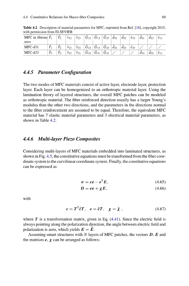
Table 4.2 Description of material parameters for MFC, reprinted from Ref. [18], copyright 2015,
with permission from ELSEVIER
MFC in fibrous
axes
˘
Y 1
˘
Y 2
˘
ν 12 ˘
ν 23
˘
G 12 ˘
G 13 ˘
G 23 ˘
d 31 ˘
d 32 ˘
33
˘
d 11 ˘
d 12 ˘
11
MFC-d31
˜
Y 1
˜
Y 2
˜
ν 12 ˜
ν 23
˜
G 12 ˜
G 13 ˜
G 23 ˜
d 31 ˜
d 32 ˜
33
MFC-d33
˜
Y 3
˜
Y 2
˜
ν 32 ˜
ν 21
˜
G 32 ˜
G 31 ˜
G 21
˜
d 33 ˜
d 32 ˜
11
4.4.5 Parameter Configuration
The two modes of MFC materials consist of active layer, electrode layer, protection
layer. Each layer can be homogenized to an orthotropic material layer. Using the
lamination theory of layered structures, the overall MFC patches can be modeled
as orthotropic material. The fiber reinforced direction usually has a larger Young’s
modulus than the other two directions, and the parameters in the directions normal
to the fiber reinforcement are assumed to be equal. Therefore, the equivalent MFC
material has 7 elastic material parameters and 3 electrical material parameters, as
shown in Table 4.2.
4.4.6 Multi-layer Piezo Composites
Considering multi-layers of MFC materials embedded into laminated structures, as
shown in Fig. 4.5, the constitutive equations must be transformed from the fiber coordinate system to the curvilinear coordinate system. Finally, the constitutive equations
can be expressed as
σ = cε − e
T E,
(4.65)
D = eε + χ E,
(4.66)
with
c = T
T
˘
cT , e = ˘
eT , χ = ˘
χ ,
(4.67)
where T is a transformation matrix, given in Eq. (4.41). Since the electric field is
always pointing along the polarization direction, the angle between electric field and
polarization is zero, which yields E = ˘
E.
Assuming smart structures with N layers of MFC patches, the vectors D, E and
the matrices e, χ can be arranged as follows:
69
Table 4.2 Description of material parameters for MFC, reprinted from Ref. [18], copyright 2015,
with permission from ELSEVIER
MFC in fibrous
axes
˘
Y 1
˘
Y 2
˘
ν 12 ˘
ν 23
˘
G 12 ˘
G 13 ˘
G 23 ˘
d 31 ˘
d 32 ˘
33
˘
d 11 ˘
d 12 ˘
11
MFC-d31
˜
Y 1
˜
Y 2
˜
ν 12 ˜
ν 23
˜
G 12 ˜
G 13 ˜
G 23 ˜
d 31 ˜
d 32 ˜
33
MFC-d33
˜
Y 3
˜
Y 2
˜
ν 32 ˜
ν 21
˜
G 32 ˜
G 31 ˜
G 21
˜
d 33 ˜
d 32 ˜
11
4.4.5 Parameter Configuration
The two modes of MFC materials consist of active layer, electrode layer, protection
layer. Each layer can be homogenized to an orthotropic material layer. Using the
lamination theory of layered structures, the overall MFC patches can be modeled
as orthotropic material. The fiber reinforced direction usually has a larger Young’s
modulus than the other two directions, and the parameters in the directions normal
to the fiber reinforcement are assumed to be equal. Therefore, the equivalent MFC
material has 7 elastic material parameters and 3 electrical material parameters, as
shown in Table 4.2.
4.4.6 Multi-layer Piezo Composites
Considering multi-layers of MFC materials embedded into laminated structures, as
shown in Fig. 4.5, the constitutive equations must be transformed from the fiber coordinate system to the curvilinear coordinate system. Finally, the constitutive equations
can be expressed as
σ = cε − e
T E,
(4.65)
D = eε + χ E,
(4.66)
with
c = T
T
˘
cT , e = ˘
eT , χ = ˘
χ ,
(4.67)
where T is a transformation matrix, given in Eq. (4.41). Since the electric field is
always pointing along the polarization direction, the angle between electric field and
polarization is zero, which yields E = ˘
E.
Assuming smart structures with N layers of MFC patches, the vectors D, E and
the matrices e, χ can be arranged as follows: