

3.3 Kinematics of Shell Structures
43
3.3 Kinematics of Shell Structures
3.3.1 Through-Thickness Displacement Distribution
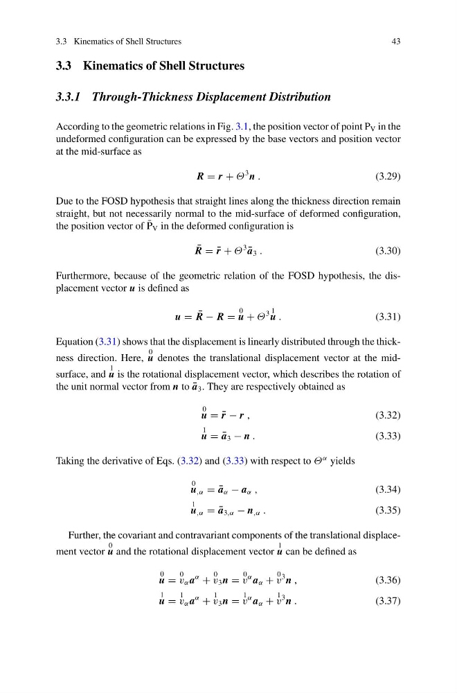
According to the geometric relations in Fig. 3.1, the position vector of point P V in the
undeformed configuration can be expressed by the base vectors and position vector
at the mid-surface as
R = r + Θ
3 n .
(3.29)
Due to the FOSD hypothesis that straight lines along the thickness direction remain
straight, but not necessarily normal to the mid-surface of deformed configuration,
the position vector of ¯
P V in the deformed configuration is
¯
R = ¯
r + Θ
3
¯
a 3 .
(3.30)
Furthermore, because of the geometric relation of the FOSD hypothesis, the displacement vector u is defined as
u = ¯
R − R =
0
u + Θ
3 1
u .
(3.31)
Equation (3.31) shows that the displacement is linearly distributed through the thickness direction. Here,
0
u denotes the translational displacement vector at the midsurface, and
1
u is the rotational displacement vector, which describes the rotation of
the unit normal vector from n to ¯
a 3 . They are respectively obtained as
0
u = ¯
r − r ,
(3.32)
1
u = ¯
a 3 − n .
(3.33)
Taking the derivative of Eqs. (3.32) and (3.33) with respect to Θ
α yields
0
u ,α = ¯
a α − a α ,
(3.34)
1
u ,α = ¯
a 3,α − n ,α .
(3.35)
Further, the covariant and contravariant components of the translational displacement vector
0
u and the rotational displacement vector
1
u can be defined as
0
u =
0
v α a
α
+
0
v 3 n =
0
v
α a α +
0
v
3 n ,
(3.36)
1
u =
1
v α a
α
+
1
v 3 n =
1
v
α a α +
1
v
3 n .
(3.37)
43
3.3 Kinematics of Shell Structures
3.3.1 Through-Thickness Displacement Distribution
According to the geometric relations in Fig. 3.1, the position vector of point P V in the
undeformed configuration can be expressed by the base vectors and position vector
at the mid-surface as
R = r + Θ
3 n .
(3.29)
Due to the FOSD hypothesis that straight lines along the thickness direction remain
straight, but not necessarily normal to the mid-surface of deformed configuration,
the position vector of ¯
P V in the deformed configuration is
¯
R = ¯
r + Θ
3
¯
a 3 .
(3.30)
Furthermore, because of the geometric relation of the FOSD hypothesis, the displacement vector u is defined as
u = ¯
R − R =
0
u + Θ
3 1
u .
(3.31)
Equation (3.31) shows that the displacement is linearly distributed through the thickness direction. Here,
0
u denotes the translational displacement vector at the midsurface, and
1
u is the rotational displacement vector, which describes the rotation of
the unit normal vector from n to ¯
a 3 . They are respectively obtained as
0
u = ¯
r − r ,
(3.32)
1
u = ¯
a 3 − n .
(3.33)
Taking the derivative of Eqs. (3.32) and (3.33) with respect to Θ
α yields
0
u ,α = ¯
a α − a α ,
(3.34)
1
u ,α = ¯
a 3,α − n ,α .
(3.35)
Further, the covariant and contravariant components of the translational displacement vector
0
u and the rotational displacement vector
1
u can be defined as
0
u =
0
v α a
α
+
0
v 3 n =
0
v
α a α +
0
v
3 n ,
(3.36)
1
u =
1
v α a
α
+
1
v 3 n =
1
v
α a α +
1
v
3 n .
(3.37)