

132
6 Nonlinear Analysis of Piezoceramic Laminated Structures
0
100
200
300
400
500
600
700
0
20
40
60
80
100
120
Electric field (V/mm)
Central point displacement (µm)
LIN5SE, present
LIN5WE, present
Material nonlinear, Abaqus
Linear, Abaqus
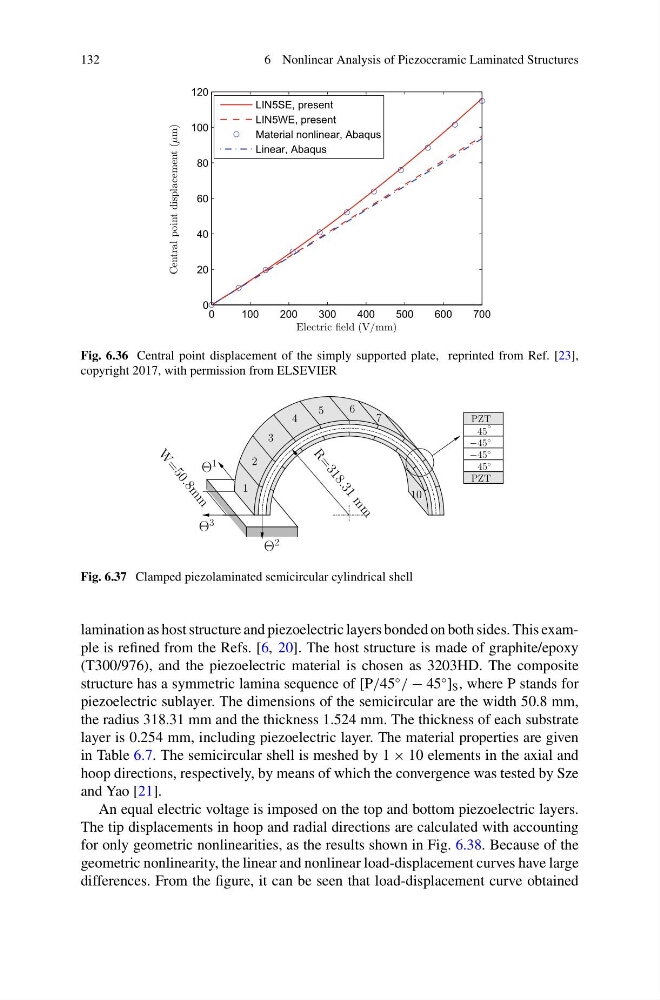
Fig. 6.36 Central point displacement of the simply supported plate, reprinted from Ref. [23],
copyright 2017, with permission from ELSEVIER
1
2
3
4
10
7
6
5
◦
−45
45
◦
−45
◦
45
PZT
PZT
R
=
3
1
8
.
3
1
m
m
W
=
5
0
.
8
m
m
◦
Θ
3
Θ
1
Θ
2
Fig. 6.37 Clamped piezolaminated semicircular cylindrical shell
lamination as host structure and piezoelectric layers bonded on both sides. This example is refined from the Refs. [6, 20]. The host structure is made of graphite/epoxy
(T300/976), and the piezoelectric material is chosen as 3203HD. The composite
structure has a symmetric lamina sequence of [P/45
◦
/ − 45
◦
] S , where P stands for
piezoelectric sublayer. The dimensions of the semicircular are the width 50.8 mm,
the radius 318.31 mm and the thickness 1.524 mm. The thickness of each substrate
layer is 0.254 mm, including piezoelectric layer. The material properties are given
in Table 6.7. The semicircular shell is meshed by 1 × 10 elements in the axial and
hoop directions, respectively, by means of which the convergence was tested by Sze
and Yao [21].
An equal electric voltage is imposed on the top and bottom piezoelectric layers.
The tip displacements in hoop and radial directions are calculated with accounting
for only geometric nonlinearities, as the results shown in Fig. 6.38. Because of the
geometric nonlinearity, the linear and nonlinear load-displacement curves have large
differences. From the figure, it can be seen that load-displacement curve obtained
6 Nonlinear Analysis of Piezoceramic Laminated Structures
0
100
200
300
400
500
600
700
0
20
40
60
80
100
120
Electric field (V/mm)
Central point displacement (µm)
LIN5SE, present
LIN5WE, present
Material nonlinear, Abaqus
Linear, Abaqus
Fig. 6.36 Central point displacement of the simply supported plate, reprinted from Ref. [23],
copyright 2017, with permission from ELSEVIER
1
2
3
4
10
7
6
5
◦
−45
45
◦
−45
◦
45
PZT
PZT
R
=
3
1
8
.
3
1
m
m
W
=
5
0
.
8
m
m
◦
Θ
3
Θ
1
Θ
2
Fig. 6.37 Clamped piezolaminated semicircular cylindrical shell
lamination as host structure and piezoelectric layers bonded on both sides. This example is refined from the Refs. [6, 20]. The host structure is made of graphite/epoxy
(T300/976), and the piezoelectric material is chosen as 3203HD. The composite
structure has a symmetric lamina sequence of [P/45
◦
/ − 45
◦
] S , where P stands for
piezoelectric sublayer. The dimensions of the semicircular are the width 50.8 mm,
the radius 318.31 mm and the thickness 1.524 mm. The thickness of each substrate
layer is 0.254 mm, including piezoelectric layer. The material properties are given
in Table 6.7. The semicircular shell is meshed by 1 × 10 elements in the axial and
hoop directions, respectively, by means of which the convergence was tested by Sze
and Yao [21].
An equal electric voltage is imposed on the top and bottom piezoelectric layers.
The tip displacements in hoop and radial directions are calculated with accounting
for only geometric nonlinearities, as the results shown in Fig. 6.38. Because of the
geometric nonlinearity, the linear and nonlinear load-displacement curves have large
differences. From the figure, it can be seen that load-displacement curve obtained