

6.4 Electroelastic Nonlinear Analysis of Smart Structures
131
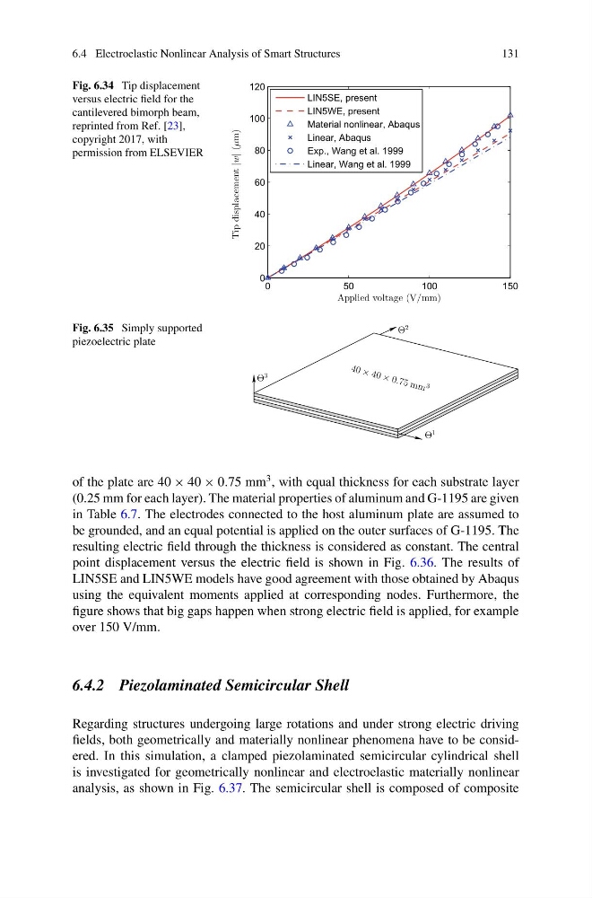
Fig. 6.34 Tip displacement
versus electric field for the
cantilevered bimorph beam,
reprinted from Ref. [23],
copyright 2017, with
permission from ELSEVIER
0
50
100
150
0
20
40
60
80
100
120
Applied voltage (V/mm)
Tip displacement
|w| (µm)
LIN5SE, present
LIN5WE, present
Material nonlinear, Abaqus
Linear, Abaqus
Exp., Wang et al. 1999
Linear, Wang et al. 1999
Fig. 6.35 Simply supported
piezoelectric plate
40 × 40 × 0. 75 m m 3
Θ
3
Θ
1
Θ
2
of the plate are 40 × 40 × 0.75 mm
3 , with equal thickness for each substrate layer
(0.25 mm for each layer). The material properties of aluminum and G-1195 are given
in Table 6.7. The electrodes connected to the host aluminum plate are assumed to
be grounded, and an equal potential is applied on the outer surfaces of G-1195. The
resulting electric field through the thickness is considered as constant. The central
point displacement versus the electric field is shown in Fig. 6.36. The results of
LIN5SE and LIN5WE models have good agreement with those obtained by Abaqus
using the equivalent moments applied at corresponding nodes. Furthermore, the
figure shows that big gaps happen when strong electric field is applied, for example
over 150 V/mm.
6.4.2 Piezolaminated Semicircular Shell
Regarding structures undergoing large rotations and under strong electric driving
fields, both geometrically and materially nonlinear phenomena have to be considered. In this simulation, a clamped piezolaminated semicircular cylindrical shell
is investigated for geometrically nonlinear and electroelastic materially nonlinear
analysis, as shown in Fig. 6.37. The semicircular shell is composed of composite
131
Fig. 6.34 Tip displacement
versus electric field for the
cantilevered bimorph beam,
reprinted from Ref. [23],
copyright 2017, with
permission from ELSEVIER
0
50
100
150
0
20
40
60
80
100
120
Applied voltage (V/mm)
Tip displacement
|w| (µm)
LIN5SE, present
LIN5WE, present
Material nonlinear, Abaqus
Linear, Abaqus
Exp., Wang et al. 1999
Linear, Wang et al. 1999
Fig. 6.35 Simply supported
piezoelectric plate
40 × 40 × 0. 75 m m 3
Θ
3
Θ
1
Θ
2
of the plate are 40 × 40 × 0.75 mm
3 , with equal thickness for each substrate layer
(0.25 mm for each layer). The material properties of aluminum and G-1195 are given
in Table 6.7. The electrodes connected to the host aluminum plate are assumed to
be grounded, and an equal potential is applied on the outer surfaces of G-1195. The
resulting electric field through the thickness is considered as constant. The central
point displacement versus the electric field is shown in Fig. 6.36. The results of
LIN5SE and LIN5WE models have good agreement with those obtained by Abaqus
using the equivalent moments applied at corresponding nodes. Furthermore, the
figure shows that big gaps happen when strong electric field is applied, for example
over 150 V/mm.
6.4.2 Piezolaminated Semicircular Shell
Regarding structures undergoing large rotations and under strong electric driving
fields, both geometrically and materially nonlinear phenomena have to be considered. In this simulation, a clamped piezolaminated semicircular cylindrical shell
is investigated for geometrically nonlinear and electroelastic materially nonlinear
analysis, as shown in Fig. 6.37. The semicircular shell is composed of composite