

5.10.1 Controlled Expansion of the Oxygen System/Vacuum
System
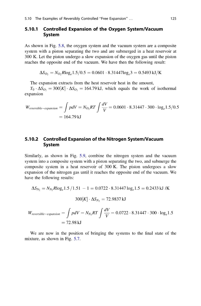
As shown in Fig. 5.8, the oxygen system and the vacuum system are a composite
system with a piston separating the two and are submerged in a heat reservoir at
300 K. Let the piston undergo a slow expansion of the oxygen gas until the piston
reaches the opposite end of the vacuum. We have then the following result:
DS O 2 ¼ N O 2 Rlog e 1:5=0:5 ¼ 0:0601 Á 8:31447log e 3 ¼ 0:5493 kJ=K
The expansion extracts from the heat reservoir heat in the amount,
T 0 Á DS O 2 ¼ 300 K
½ Á DS O 2 ¼ 164:79 kJ, which equals the work of isothermal
expansion
W reversibleÀexpansion ¼
Z
pdV ¼ N O 2 RT
Z dV
V
¼ 0:0601 Á 8:31447 Á 300 Á log e 1:5=0:5
¼ 164:79 kJ
5.10.2 Controlled Expansion of the Nitrogen System/Vacuum
System
Similarly, as shown in Fig. 5.9, combine the nitrogen system and the vacuum
system into a composite system with a piston separating the two, and submerge the
composite system in a heat reservoir of 300 K. The piston undergoes a slow
expansion of the nitrogen gas until it reaches the opposite end of the vacuum. We
have the following results:
DS N 2 ¼ N N 2 Rlog e 1:5 =1:51 À 1 ¼ 0:0722 Á 8:31447 log e 1:5 ¼ 0:2433 kJ /K
300 K
½ Á DS N 2 ¼ 72:9837 kJ
W reversibleÀexpansion ¼
Z
pdV ¼ N N 2 RT
Z dV
V
¼ 0:0722 Á 8:31447 Á 300 Á log e 1:5
¼ 72:98 kJ
We are now in the position of bringing the systems to the final state of the
mixture, as shown in Fig. 5.7.
5.10 The Examples of Reversibly Controlled “Free Expansion” …
125
System
As shown in Fig. 5.8, the oxygen system and the vacuum system are a composite
system with a piston separating the two and are submerged in a heat reservoir at
300 K. Let the piston undergo a slow expansion of the oxygen gas until the piston
reaches the opposite end of the vacuum. We have then the following result:
DS O 2 ¼ N O 2 Rlog e 1:5=0:5 ¼ 0:0601 Á 8:31447log e 3 ¼ 0:5493 kJ=K
The expansion extracts from the heat reservoir heat in the amount,
T 0 Á DS O 2 ¼ 300 K
½ Á DS O 2 ¼ 164:79 kJ, which equals the work of isothermal
expansion
W reversibleÀexpansion ¼
Z
pdV ¼ N O 2 RT
Z dV
V
¼ 0:0601 Á 8:31447 Á 300 Á log e 1:5=0:5
¼ 164:79 kJ
5.10.2 Controlled Expansion of the Nitrogen System/Vacuum
System
Similarly, as shown in Fig. 5.9, combine the nitrogen system and the vacuum
system into a composite system with a piston separating the two, and submerge the
composite system in a heat reservoir of 300 K. The piston undergoes a slow
expansion of the nitrogen gas until it reaches the opposite end of the vacuum. We
have the following results:
DS N 2 ¼ N N 2 Rlog e 1:5 =1:51 À 1 ¼ 0:0722 Á 8:31447 log e 1:5 ¼ 0:2433 kJ /K
300 K
½ Á DS N 2 ¼ 72:9837 kJ
W reversibleÀexpansion ¼
Z
pdV ¼ N N 2 RT
Z dV
V
¼ 0:0722 Á 8:31447 Á 300 Á log e 1:5
¼ 72:98 kJ
We are now in the position of bringing the systems to the final state of the
mixture, as shown in Fig. 5.7.
5.10 The Examples of Reversibly Controlled “Free Expansion” …
125