

102
6 Mechanical characterization on sub-component level
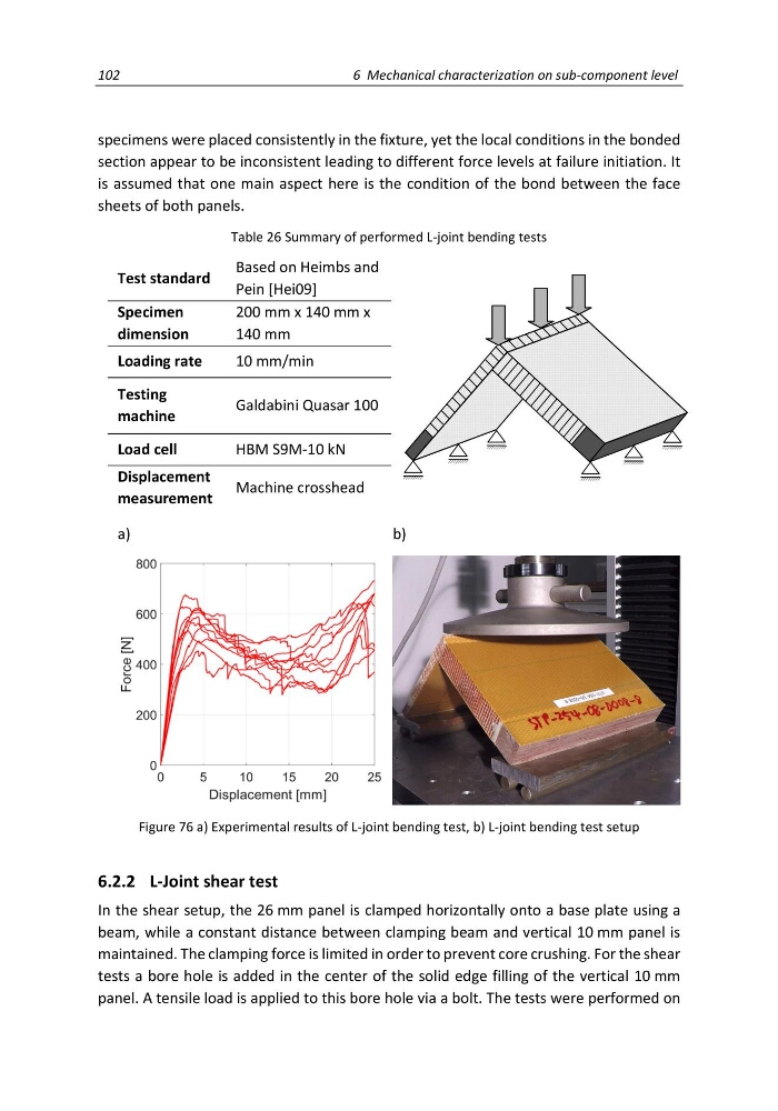
specimens were placed consistently in the fixture, yet the local conditions in the bonded
section appear to be inconsistent leading to different force levels at failure initiation. It
is assumed that one main aspect here is the condition of the bond between the face
sheets of both panels.
Table 26 Summary of performed L-joint bending tests
Test standard
Based on Heimbs and
Pein [Hei09]
Specimen
dimension
200 mm x 140 mm x
140 mm
Loading rate
10 mm/min
Testing
machine
Galdabini Quasar 100
Load cell
HBM S9M-10 kN
Displacement
measurement
Machine crosshead
a)
b)
Figure 76 a) Experimental results of L-joint bending test, b) L-joint bending test setup
6.2.2 L-Joint shear test
In the shear setup, the 26 mm panel is clamped horizontally onto a base plate using a
beam, while a constant distance between clamping beam and vertical 10 mm panel is
maintained. The clamping force is limited in order to prevent core crushing. For the shear
tests a bore hole is added in the center of the solid edge filling of the vertical 10 mm
panel. A tensile load is applied to this bore hole via a bolt. The tests were performed on
6 Mechanical characterization on sub-component level
specimens were placed consistently in the fixture, yet the local conditions in the bonded
section appear to be inconsistent leading to different force levels at failure initiation. It
is assumed that one main aspect here is the condition of the bond between the face
sheets of both panels.
Table 26 Summary of performed L-joint bending tests
Test standard
Based on Heimbs and
Pein [Hei09]
Specimen
dimension
200 mm x 140 mm x
140 mm
Loading rate
10 mm/min
Testing
machine
Galdabini Quasar 100
Load cell
HBM S9M-10 kN
Displacement
measurement
Machine crosshead
a)
b)
Figure 76 a) Experimental results of L-joint bending test, b) L-joint bending test setup
6.2.2 L-Joint shear test
In the shear setup, the 26 mm panel is clamped horizontally onto a base plate using a
beam, while a constant distance between clamping beam and vertical 10 mm panel is
maintained. The clamping force is limited in order to prevent core crushing. For the shear
tests a bore hole is added in the center of the solid edge filling of the vertical 10 mm
panel. A tensile load is applied to this bore hole via a bolt. The tests were performed on