

88
5 Mechanical characterization on structural element level
Table 22 Summary of performed frame shear tests
Test standard
ASTM D8067/D8067M
[AST17]
Specimen
dimension
400 mm x 400 mm,
Type A no edge doublers, potting in the
clamping area
Loading rate
10 mm/min
Testing
machine
Galdabini Quasar 100
Load cell
HBM S9M-50 kN
Strain
measurement
Strain gauge, HBM 1RY18-6/120 (rosette)
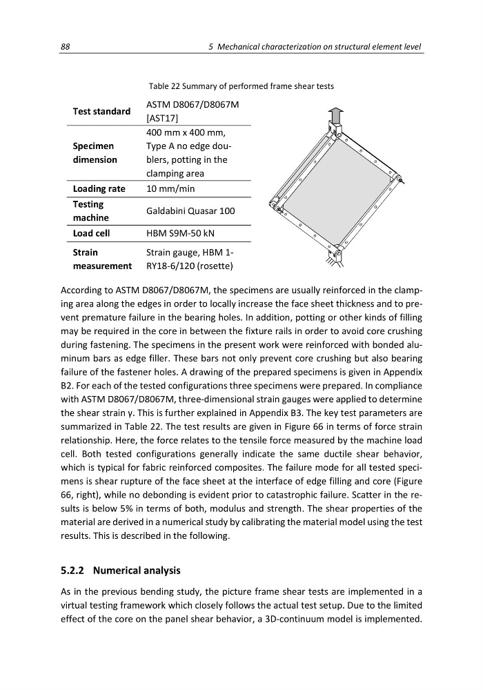
According to ASTM D8067/D8067M, the specimens are usually reinforced in the clamping area along the edges in order to locally increase the face sheet thickness and to prevent premature failure in the bearing holes. In addition, potting or other kinds of filling
may be required in the core in between the fixture rails in order to avoid core crushing
during fastening. The specimens in the present work were reinforced with bonded aluminum bars as edge filler. These bars not only prevent core crushing but also bearing
failure of the fastener holes. A drawing of the prepared specimens is given in Appendix
B2. For each of the tested configurations three specimens were prepared. In compliance
with ASTM D8067/D8067M, three-dimensional strain gauges were applied to determine
the shear strain γ. This is further explained in Appendix B3. The key test parameters are
summarized in Table 22. The test results are given in Figure 66 in terms of force strain
relationship. Here, the force relates to the tensile force measured by the machine load
cell. Both tested configurations generally indicate the same ductile shear behavior,
which is typical for fabric reinforced composites. The failure mode for all tested specimens is shear rupture of the face sheet at the interface of edge filling and core (Figure
66, right), while no debonding is evident prior to catastrophic failure. Scatter in the results is below 5% in terms of both, modulus and strength. The shear properties of the
material are derived in a numerical study by calibrating the material model using the test
results. This is described in the following.
5.2.2 Numerical analysis
As in the previous bending study, the picture frame shear tests are implemented in a
virtual testing framework which closely follows the actual test setup. Due to the limited
effect of the core on the panel shear behavior, a 3D-continuum model is implemented.
5 Mechanical characterization on structural element level
Table 22 Summary of performed frame shear tests
Test standard
ASTM D8067/D8067M
[AST17]
Specimen
dimension
400 mm x 400 mm,
Type A no edge doublers, potting in the
clamping area
Loading rate
10 mm/min
Testing
machine
Galdabini Quasar 100
Load cell
HBM S9M-50 kN
Strain
measurement
Strain gauge, HBM 1RY18-6/120 (rosette)
According to ASTM D8067/D8067M, the specimens are usually reinforced in the clamping area along the edges in order to locally increase the face sheet thickness and to prevent premature failure in the bearing holes. In addition, potting or other kinds of filling
may be required in the core in between the fixture rails in order to avoid core crushing
during fastening. The specimens in the present work were reinforced with bonded aluminum bars as edge filler. These bars not only prevent core crushing but also bearing
failure of the fastener holes. A drawing of the prepared specimens is given in Appendix
B2. For each of the tested configurations three specimens were prepared. In compliance
with ASTM D8067/D8067M, three-dimensional strain gauges were applied to determine
the shear strain γ. This is further explained in Appendix B3. The key test parameters are
summarized in Table 22. The test results are given in Figure 66 in terms of force strain
relationship. Here, the force relates to the tensile force measured by the machine load
cell. Both tested configurations generally indicate the same ductile shear behavior,
which is typical for fabric reinforced composites. The failure mode for all tested specimens is shear rupture of the face sheet at the interface of edge filling and core (Figure
66, right), while no debonding is evident prior to catastrophic failure. Scatter in the results is below 5% in terms of both, modulus and strength. The shear properties of the
material are derived in a numerical study by calibrating the material model using the test
results. This is described in the following.
5.2.2 Numerical analysis
As in the previous bending study, the picture frame shear tests are implemented in a
virtual testing framework which closely follows the actual test setup. Due to the limited
effect of the core on the panel shear behavior, a 3D-continuum model is implemented.