

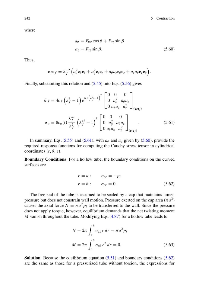
242
5 Contraction
where
a θ = F θθ cos β + F θz sin β
a z = F zz sin β.
(5.60)
Thus,
e f e f = λ
−2
f
a
2
θ e θ e θ + a
2
z e z e z + a θ a z e θ e z + a z a θ e z e θ
.
Finally, substituting this relation and (5.45) into Eqs. (5.56) gives
¯
σ f = 4c f
λ
2
f − 1
e
α f
λ 2
f −1
2
⎡
⎣
0 0
0
0 a 2
θ a θ a z
0 a θ a z a 2
z
⎤
⎦
(e i e j )
σ a = 8c a (t)
λ ∗2
f
λ 2
f
λ
∗2
f − 1
3
⎡
⎣
0 0
0
0 a 2
θ a θ a z
0 a θ a z a 2
z
⎤
⎦
(e i e j )
.
(5.61)
In summary, Eqs. (5.55) and (5.61), with a θ and a z given by (5.60), provide the
required response functions for computing the Cauchy stress tensor in cylindrical
coordinates (r, θ, z).
Boundary Conditions For a hollow tube, the boundary conditions on the curved
surfaces are
r = a :
σ rr = −p i
r = b :
σ rr = 0.
(5.62)
The free end of the tube is assumed to be sealed by a cap that maintains lumen
pressure but does not constrain wall motion. Pressure exerted on the cap area (πa 2 )
causes the axial force N = πa 2 p i to be transferred to the wall. Since the pressure
does not apply torque, however, equilibrium demands that the net twisting moment
M vanish throughout the tube. Modifying Eqs. (4.87) for a hollow tube leads to
N = 2π
b
a
σ zz r dr = πa
2 p i
M = 2π
b
a
σ zθ r
2 dr = 0.
(5.63)
Solution Because the equilibrium equation (5.51) and boundary conditions (5.62)
are the same as those for a pressurized tube without torsion, the expressions for
5 Contraction
where
a θ = F θθ cos β + F θz sin β
a z = F zz sin β.
(5.60)
Thus,
e f e f = λ
−2
f
a
2
θ e θ e θ + a
2
z e z e z + a θ a z e θ e z + a z a θ e z e θ
.
Finally, substituting this relation and (5.45) into Eqs. (5.56) gives
¯
σ f = 4c f
λ
2
f − 1
e
α f
λ 2
f −1
2
⎡
⎣
0 0
0
0 a 2
θ a θ a z
0 a θ a z a 2
z
⎤
⎦
(e i e j )
σ a = 8c a (t)
λ ∗2
f
λ 2
f
λ
∗2
f − 1
3
⎡
⎣
0 0
0
0 a 2
θ a θ a z
0 a θ a z a 2
z
⎤
⎦
(e i e j )
.
(5.61)
In summary, Eqs. (5.55) and (5.61), with a θ and a z given by (5.60), provide the
required response functions for computing the Cauchy stress tensor in cylindrical
coordinates (r, θ, z).
Boundary Conditions For a hollow tube, the boundary conditions on the curved
surfaces are
r = a :
σ rr = −p i
r = b :
σ rr = 0.
(5.62)
The free end of the tube is assumed to be sealed by a cap that maintains lumen
pressure but does not constrain wall motion. Pressure exerted on the cap area (πa 2 )
causes the axial force N = πa 2 p i to be transferred to the wall. Since the pressure
does not apply torque, however, equilibrium demands that the net twisting moment
M vanish throughout the tube. Modifying Eqs. (4.87) for a hollow tube leads to
N = 2π
b
a
σ zz r dr = πa
2 p i
M = 2π
b
a
σ zθ r
2 dr = 0.
(5.63)
Solution Because the equilibrium equation (5.51) and boundary conditions (5.62)
are the same as those for a pressurized tube without torsion, the expressions for