

200
4 Problems in Soft Tissue Biomechanics
Boundary conditions at the ends of the deformed block furnish the applied loads.
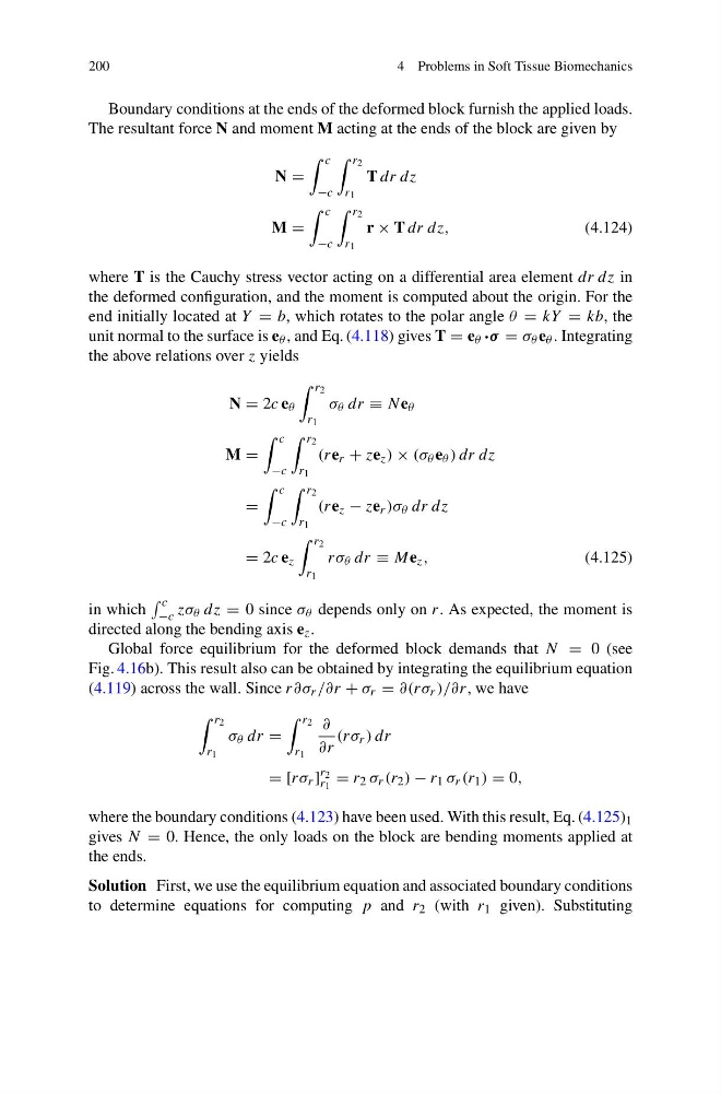
The resultant force N and moment M acting at the ends of the block are given by
N =
c
−c
r 2
r 1
T dr dz
M =
c
−c
r 2
r 1
r × T dr dz,
(4.124)
where T is the Cauchy stress vector acting on a differential area element dr dz in
the deformed configuration, and the moment is computed about the origin. For the
end initially located at Y = b, which rotates to the polar angle θ = kY = kb, the
unit normal to the surface is e θ , and Eq. (4.118) gives T = e θ ·σ = σ θ e θ . Integrating
the above relations over z yields
N = 2c e θ
r 2
r 1
σ θ dr ≡ N e θ
M =
c
−c
r 2
r 1
(re r + ze z ) × (σ θ e θ ) dr dz
=
c
−c
r 2
r 1
(re z − ze r )σ θ dr dz
= 2c e z
r 2
r 1
rσ θ dr ≡ Me z ,
(4.125)
in which
c
−c zσ θ dz = 0 since σ θ depends only on r. As expected, the moment is
directed along the bending axis e z .
Global force equilibrium for the deformed block demands that N = 0 (see
Fig. 4.16b). This result also can be obtained by integrating the equilibrium equation
(4.119) across the wall. Since r∂σ r /∂r + σ r = ∂(rσ r )/∂r, we have
r 2
r 1
σ θ dr =
r 2
r 1
∂
∂r
(rσ r ) dr
= [rσ r ]
r 2
r 1
= r 2 σ r (r 2 ) − r 1 σ r (r 1 ) = 0,
where the boundary conditions (4.123) have been used. With this result, Eq. (4.125) 1
gives N = 0. Hence, the only loads on the block are bending moments applied at
the ends.
Solution First, we use the equilibrium equation and associated boundary conditions
to determine equations for computing p and r 2 (with r 1 given). Substituting
4 Problems in Soft Tissue Biomechanics
Boundary conditions at the ends of the deformed block furnish the applied loads.
The resultant force N and moment M acting at the ends of the block are given by
N =
c
−c
r 2
r 1
T dr dz
M =
c
−c
r 2
r 1
r × T dr dz,
(4.124)
where T is the Cauchy stress vector acting on a differential area element dr dz in
the deformed configuration, and the moment is computed about the origin. For the
end initially located at Y = b, which rotates to the polar angle θ = kY = kb, the
unit normal to the surface is e θ , and Eq. (4.118) gives T = e θ ·σ = σ θ e θ . Integrating
the above relations over z yields
N = 2c e θ
r 2
r 1
σ θ dr ≡ N e θ
M =
c
−c
r 2
r 1
(re r + ze z ) × (σ θ e θ ) dr dz
=
c
−c
r 2
r 1
(re z − ze r )σ θ dr dz
= 2c e z
r 2
r 1
rσ θ dr ≡ Me z ,
(4.125)
in which
c
−c zσ θ dz = 0 since σ θ depends only on r. As expected, the moment is
directed along the bending axis e z .
Global force equilibrium for the deformed block demands that N = 0 (see
Fig. 4.16b). This result also can be obtained by integrating the equilibrium equation
(4.119) across the wall. Since r∂σ r /∂r + σ r = ∂(rσ r )/∂r, we have
r 2
r 1
σ θ dr =
r 2
r 1
∂
∂r
(rσ r ) dr
= [rσ r ]
r 2
r 1
= r 2 σ r (r 2 ) − r 1 σ r (r 1 ) = 0,
where the boundary conditions (4.123) have been used. With this result, Eq. (4.125) 1
gives N = 0. Hence, the only loads on the block are bending moments applied at
the ends.
Solution First, we use the equilibrium equation and associated boundary conditions
to determine equations for computing p and r 2 (with r 1 given). Substituting