

328
P. Liu
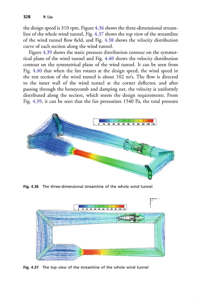
the design speed is 310 rpm. Figure 4.36 shows the three-dimensional streamline of the whole wind tunnel, Fig. 4.37 shows the top view of the streamline
of the wind tunnel flow field, and Fig. 4.38 shows the velocity distribution
curve of each section along the wind tunnel.
Figure 4.39 shows the static pressure distribution contour on the symmetrical plane of the wind tunnel and Fig. 4.40 shows the velocity distribution
contour on the symmetrical plane of the wind tunnel. It can be seen from
Fig. 4.40 that when the fan rotates at the design speed, the wind speed in
the test section of the wind tunnel is about 102 m/s. The flow is directed
to the inner wall of the wind tunnel at the corner deflector, and after
passing through the honeycomb and damping net, the velocity is uniformly
distributed along the section, which meets the design requirements. From
Fig. 4.39, it can be seen that the fan pressurizes 1540 Pa, the total pressure
Fig. 4.36 The three-dimensional streamline of the whole wind tunnel
Fig. 4.37 The top view of the streamline of the whole wind tunnel
P. Liu
the design speed is 310 rpm. Figure 4.36 shows the three-dimensional streamline of the whole wind tunnel, Fig. 4.37 shows the top view of the streamline
of the wind tunnel flow field, and Fig. 4.38 shows the velocity distribution
curve of each section along the wind tunnel.
Figure 4.39 shows the static pressure distribution contour on the symmetrical plane of the wind tunnel and Fig. 4.40 shows the velocity distribution
contour on the symmetrical plane of the wind tunnel. It can be seen from
Fig. 4.40 that when the fan rotates at the design speed, the wind speed in
the test section of the wind tunnel is about 102 m/s. The flow is directed
to the inner wall of the wind tunnel at the corner deflector, and after
passing through the honeycomb and damping net, the velocity is uniformly
distributed along the section, which meets the design requirements. From
Fig. 4.39, it can be seen that the fan pressurizes 1540 Pa, the total pressure
Fig. 4.36 The three-dimensional streamline of the whole wind tunnel
Fig. 4.37 The top view of the streamline of the whole wind tunnel