

222
P. Liu
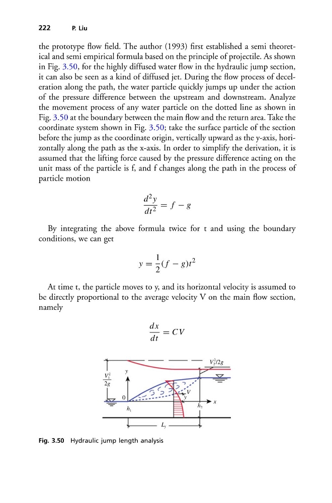
the prototype flow field. The author (1993) first established a semi theoretical and semi empirical formula based on the principle of projectile. As shown
in Fig. 3.50, for the highly diffused water flow in the hydraulic jump section,
it can also be seen as a kind of diffused jet. During the flow process of deceleration along the path, the water particle quickly jumps up under the action
of the pressure difference between the upstream and downstream. Analyze
the movement process of any water particle on the dotted line as shown in
Fig. 3.50 at the boundary between the main flow and the return area. Take the
coordinate system shown in Fig. 3.50; take the surface particle of the section
before the jump as the coordinate origin, vertically upward as the y-axis, horizontally along the path as the x-axis. In order to simplify the derivation, it is
assumed that the lifting force caused by the pressure difference acting on the
unit mass of the particle is f, and f changes along the path in the process of
particle motion
d 2 y
dt 2 = f − g
By integrating the above formula twice for t and using the boundary
conditions, we can get
y =
1
2
( f − g)t
2
At time t, the particle moves to y, and its horizontal velocity is assumed to
be directly proportional to the average velocity V on the main flow section,
namely
dx
dt
= C V
y
0
h 1
L j
h 2
x
y
V
V 2
2
/2g
V 1
2
2g
Fig. 3.50 Hydraulic jump length analysis
P. Liu
the prototype flow field. The author (1993) first established a semi theoretical and semi empirical formula based on the principle of projectile. As shown
in Fig. 3.50, for the highly diffused water flow in the hydraulic jump section,
it can also be seen as a kind of diffused jet. During the flow process of deceleration along the path, the water particle quickly jumps up under the action
of the pressure difference between the upstream and downstream. Analyze
the movement process of any water particle on the dotted line as shown in
Fig. 3.50 at the boundary between the main flow and the return area. Take the
coordinate system shown in Fig. 3.50; take the surface particle of the section
before the jump as the coordinate origin, vertically upward as the y-axis, horizontally along the path as the x-axis. In order to simplify the derivation, it is
assumed that the lifting force caused by the pressure difference acting on the
unit mass of the particle is f, and f changes along the path in the process of
particle motion
d 2 y
dt 2 = f − g
By integrating the above formula twice for t and using the boundary
conditions, we can get
y =
1
2
( f − g)t
2
At time t, the particle moves to y, and its horizontal velocity is assumed to
be directly proportional to the average velocity V on the main flow section,
namely
dx
dt
= C V
y
0
h 1
L j
h 2
x
y
V
V 2
2
/2g
V 1
2
2g
Fig. 3.50 Hydraulic jump length analysis