

214
P. Liu
is proportional to the power of 1.5 of the total head of the weir crest. The
discharge coefficient m is mainly determined by experiments, and the value
is different for different weir flows.
(2) Gate outlet
The gate installed on the top of the channel or weir can be used to adjust the
discharge and water level, so the main task of the gate outlet flow calculation
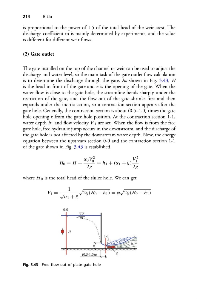
is to determine the discharge through the gate. As shown in Fig. 3.43, H
is the head in front of the gate and e is the opening of the gate. When the
water flow is close to the gate hole, the streamline bends sharply under the
restriction of the gate, and the flow out of the gate shrinks first and then
expands under the inertia action, so a contraction section appears after the
gate hole. Generally, the contraction section is about (0.5–1.0) times the gate
hole opening e from the gate hole position. At the contraction section 1-1,
water depth h 1 and flow velocity V 1 are set. When the flow is from the free
gate hole, free hydraulic jump occurs in the downstream, and the discharge of
the gate hole is not affected by the downstream water depth. Now, the energy
equation between the upstream section 0-0 and the contraction section 1-1
of the gate shown in Fig. 3.43 is established
H 0 = H +
α 0 V 2
0
2g
= h 1 + (α 1 + ξ )
V 2
1
2g
where H 0 is the total head of the sluice hole. We can get
V 1 =
1
√ α 1 + ξ
2g(H 0 − h 1 ) = ϕ
2g(H 0 − h 1 )
Fig. 3.43 Free flow out of plate gate hole
P. Liu
is proportional to the power of 1.5 of the total head of the weir crest. The
discharge coefficient m is mainly determined by experiments, and the value
is different for different weir flows.
(2) Gate outlet
The gate installed on the top of the channel or weir can be used to adjust the
discharge and water level, so the main task of the gate outlet flow calculation
is to determine the discharge through the gate. As shown in Fig. 3.43, H
is the head in front of the gate and e is the opening of the gate. When the
water flow is close to the gate hole, the streamline bends sharply under the
restriction of the gate, and the flow out of the gate shrinks first and then
expands under the inertia action, so a contraction section appears after the
gate hole. Generally, the contraction section is about (0.5–1.0) times the gate
hole opening e from the gate hole position. At the contraction section 1-1,
water depth h 1 and flow velocity V 1 are set. When the flow is from the free
gate hole, free hydraulic jump occurs in the downstream, and the discharge of
the gate hole is not affected by the downstream water depth. Now, the energy
equation between the upstream section 0-0 and the contraction section 1-1
of the gate shown in Fig. 3.43 is established
H 0 = H +
α 0 V 2
0
2g
= h 1 + (α 1 + ξ )
V 2
1
2g
where H 0 is the total head of the sluice hole. We can get
V 1 =
1
√ α 1 + ξ
2g(H 0 − h 1 ) = ϕ
2g(H 0 − h 1 )
Fig. 3.43 Free flow out of plate gate hole