

3 Hydrodynamics
189
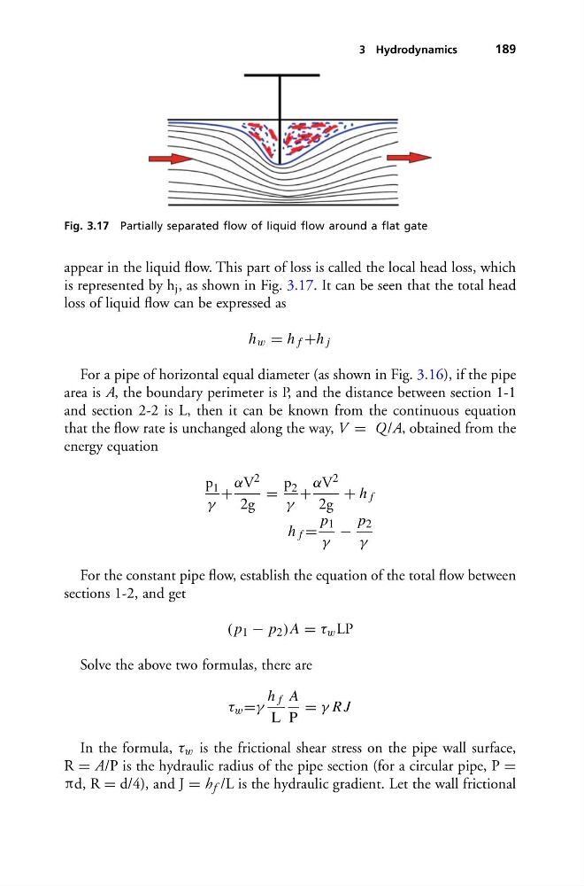
Fig. 3.17 Partially separated flow of liquid flow around a flat gate
appear in the liquid flow. This part of loss is called the local head loss, which
is represented by h j , as shown in Fig. 3.17. It can be seen that the total head
loss of liquid flow can be expressed as
h w = h f +h j
For a pipe of horizontal equal diameter (as shown in Fig. 3.16), if the pipe
area is A, the boundary perimeter is P, and the distance between section 1-1
and section 2-2 is L, then it can be known from the continuous equation
that the flow rate is unchanged along the way, V = Q /A, obtained from the
energy equation
p 1
γ
+
αV 2
2g
=
p 2
γ
+
αV 2
2g
+ h f
h f =
p 1
γ
−
p 2
γ
For the constant pipe flow, establish the equation of the total flow between
sections 1-2, and get
( p 1 − p 2 )A = τ w LP
Solve the above two formulas, there are
τ w =γ
h f
L
A
P
= γ R J
In the formula, τ w is the frictional shear stress on the pipe wall surface,
R = A/P is the hydraulic radius of the pipe section (for a circular pipe, P =
πd, R = d/4), and J = h f /L is the hydraulic gradient. Let the wall frictional
189
Fig. 3.17 Partially separated flow of liquid flow around a flat gate
appear in the liquid flow. This part of loss is called the local head loss, which
is represented by h j , as shown in Fig. 3.17. It can be seen that the total head
loss of liquid flow can be expressed as
h w = h f +h j
For a pipe of horizontal equal diameter (as shown in Fig. 3.16), if the pipe
area is A, the boundary perimeter is P, and the distance between section 1-1
and section 2-2 is L, then it can be known from the continuous equation
that the flow rate is unchanged along the way, V = Q /A, obtained from the
energy equation
p 1
γ
+
αV 2
2g
=
p 2
γ
+
αV 2
2g
+ h f
h f =
p 1
γ
−
p 2
γ
For the constant pipe flow, establish the equation of the total flow between
sections 1-2, and get
( p 1 − p 2 )A = τ w LP
Solve the above two formulas, there are
τ w =γ
h f
L
A
P
= γ R J
In the formula, τ w is the frictional shear stress on the pipe wall surface,
R = A/P is the hydraulic radius of the pipe section (for a circular pipe, P =
πd, R = d/4), and J = h f /L is the hydraulic gradient. Let the wall frictional