

LAGP (for two systems), and the preferred path is a path having low activation
energy. The voltage stability window was broader (~5.12 V) as compared to pure
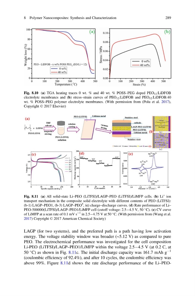
PEO. The electrochemical performance was investigated for the cell composition
Li-PEO (LiTFSI)/LAGP–PEO1/LiMFP within the voltage 2.5À4.5 V (at 0.2 C, at
50
C) as shown in Fig. 8.11c. The initial discharge capacity was 161.7 mAh g
À1
(coulombic efficiency of 92.4%), and after 10 cycles, the coulombic efficiency was
above 99%. Figure 8.11d shows the rate discharge performance of the Li–PEOFig. 8.10 (a) TGA heating traces 0 wt. % and 40 wt. % POSS–PEG doped PEO 12 :LiDFOB
electrolyte membranes and (b) stress–strain curves of PEO 12 :LiDFOB and PEO 12 :LiDFOB:40
wt. % POSS–PEG polymer electrolyte membranes. (With permission from (Polu et al. 2017),
Copyright © 2017 Elsevier)
Fig. 8.11 (a) All solid-state Li–PEO (LiTFSI)/LAGP–PEO (LiTFSI)/LiMFP cells. (b) Li
+ ion
transport mechanism in the composite solid electrolyte with different contents of PEO (LiTFSI):
(b-1) LAGP–PEO1, (b-3) LAGP–PEO
5
, (c) charge–discharge curves. (d) Rate performance of Li–
PEO-500000(LiTFSI)/LAGP–PEO1/LiMFP cell (cutoff voltage: 2.5À4.5 V, 50
C). (e) CV curve
of LiMFP at a scan rate of 0.1 mV s
À1 in 2.5À4.75 V at 50
C. (With permission from (Wang et al.
2017) Copyright © 2017 American Chemical Society)
8 Polymer Nanocomposites: Synthesis and Characterization
289
energy. The voltage stability window was broader (~5.12 V) as compared to pure
PEO. The electrochemical performance was investigated for the cell composition
Li-PEO (LiTFSI)/LAGP–PEO1/LiMFP within the voltage 2.5À4.5 V (at 0.2 C, at
50
C) as shown in Fig. 8.11c. The initial discharge capacity was 161.7 mAh g
À1
(coulombic efficiency of 92.4%), and after 10 cycles, the coulombic efficiency was
above 99%. Figure 8.11d shows the rate discharge performance of the Li–PEOFig. 8.10 (a) TGA heating traces 0 wt. % and 40 wt. % POSS–PEG doped PEO 12 :LiDFOB
electrolyte membranes and (b) stress–strain curves of PEO 12 :LiDFOB and PEO 12 :LiDFOB:40
wt. % POSS–PEG polymer electrolyte membranes. (With permission from (Polu et al. 2017),
Copyright © 2017 Elsevier)
Fig. 8.11 (a) All solid-state Li–PEO (LiTFSI)/LAGP–PEO (LiTFSI)/LiMFP cells. (b) Li
+ ion
transport mechanism in the composite solid electrolyte with different contents of PEO (LiTFSI):
(b-1) LAGP–PEO1, (b-3) LAGP–PEO
5
, (c) charge–discharge curves. (d) Rate performance of Li–
PEO-500000(LiTFSI)/LAGP–PEO1/LiMFP cell (cutoff voltage: 2.5À4.5 V, 50
C). (e) CV curve
of LiMFP at a scan rate of 0.1 mV s
À1 in 2.5À4.75 V at 50
C. (With permission from (Wang et al.
2017) Copyright © 2017 American Chemical Society)
8 Polymer Nanocomposites: Synthesis and Characterization
289