

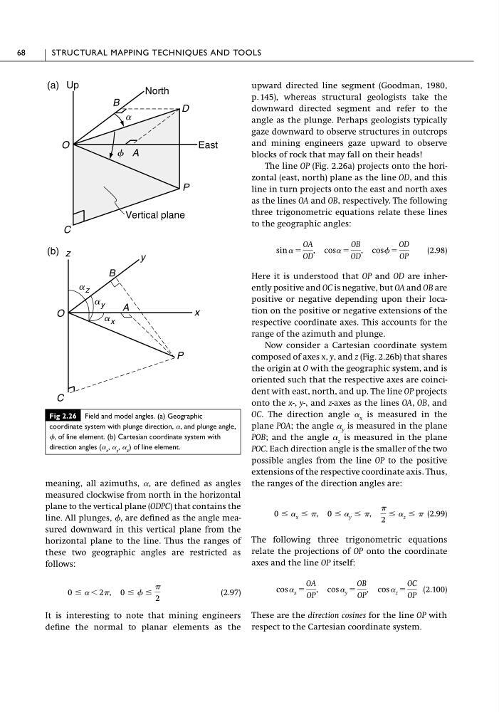
meaning, all azimuths, ␣, are defined as angles
measured clockwise from north in the horizontal
plane to the vertical plane (ODPC) that contains the
line. All plunges, , are defined as the angle measured downward in this vertical plane from the
horizontal plane to the line. Thus the ranges of
these two geographic angles are restricted as
follows:
(2.97)
It is interesting to note that mining engineers
define the normal to planar elements as the
0 Յ ␣ Ͻ 2, 0 Յ Յ
2
upward directed line segment (Goodman, 1980,
p. 145), whereas structural geologists take the
downward directed segment and refer to the
angle as the plunge. Perhaps geologists typically
gaze downward to observe structures in outcrops
and mining engineers gaze upward to observe
blocks of rock that may fall on their heads!
The line OP (Fig. 2.26a) projects onto the horizontal (east, north) plane as the line OD, and this
line in turn projects onto the east and north axes
as the lines OA and OB, respectively. The following
three trigonometric equations relate these lines
to the geographic angles:
(2.98)
Here it is understood that OP and OD are inherently positive and OC is negative, but OA and OB are
positive or negative depending upon their location on the positive or negative extensions of the
respective coordinate axes. This accounts for the
range of the azimuth and plunge.
Now consider a Cartesian coordinate system
composed of axes x, y, and z (Fig. 2.26b) that shares
the origin at O with the geographic system, and is
oriented such that the respective axes are coincident with east, north, and up. The line OP projects
onto the x-, y-, and z-axes as the lines OA, OB, and
OC. The direction angle ␣ x is measured in the
plane POA; the angle ␣ y is measured in the plane
POB; and the angle ␣ z is measured in the plane
POC. Each direction angle is the smaller of the two
possible angles from the line OP to the positive
extensions of the respective coordinate axis. Thus,
the ranges of the direction angles are:
(2.99)
The following three trigonometric equations
relate the projections of OP onto the coordinate
axes and the line OP itself:
(2.100)
These are the direction cosines for the line OP with
respect to the Cartesian coordinate system.
cos ␣ x ϭ
OA
OP
, cos ␣ y ϭ
OB
OP
, cos ␣ z ϭ
OC
OP
0 Յ ␣ x Յ , 0 Յ ␣ y Յ ,
2
Յ ␣ z Յ
sin ␣ ϭ
OA
OD
, cos␣ ϭ
OB
OD
, cos ϭ
OD
OP
68
STRUCTURAL MAPPING TECHNIQUES AND TOOLS
Fig 2.26 Field and model angles. (a) Geographic
coordinate system with plunge direction, ␣, and plunge angle,
, of line element. (b) Cartesian coordinate system with
direction angles (␣ x , ␣ y , ␣ z ) of line element.
Up
(a)
North
East
Vertical plane
f
a
D
P
C
O
A
B
z
(b)
y
x
P
C
O
A
B
a z
a y
a x
measured clockwise from north in the horizontal
plane to the vertical plane (ODPC) that contains the
line. All plunges, , are defined as the angle measured downward in this vertical plane from the
horizontal plane to the line. Thus the ranges of
these two geographic angles are restricted as
follows:
(2.97)
It is interesting to note that mining engineers
define the normal to planar elements as the
0 Յ ␣ Ͻ 2, 0 Յ Յ
2
upward directed line segment (Goodman, 1980,
p. 145), whereas structural geologists take the
downward directed segment and refer to the
angle as the plunge. Perhaps geologists typically
gaze downward to observe structures in outcrops
and mining engineers gaze upward to observe
blocks of rock that may fall on their heads!
The line OP (Fig. 2.26a) projects onto the horizontal (east, north) plane as the line OD, and this
line in turn projects onto the east and north axes
as the lines OA and OB, respectively. The following
three trigonometric equations relate these lines
to the geographic angles:
(2.98)
Here it is understood that OP and OD are inherently positive and OC is negative, but OA and OB are
positive or negative depending upon their location on the positive or negative extensions of the
respective coordinate axes. This accounts for the
range of the azimuth and plunge.
Now consider a Cartesian coordinate system
composed of axes x, y, and z (Fig. 2.26b) that shares
the origin at O with the geographic system, and is
oriented such that the respective axes are coincident with east, north, and up. The line OP projects
onto the x-, y-, and z-axes as the lines OA, OB, and
OC. The direction angle ␣ x is measured in the
plane POA; the angle ␣ y is measured in the plane
POB; and the angle ␣ z is measured in the plane
POC. Each direction angle is the smaller of the two
possible angles from the line OP to the positive
extensions of the respective coordinate axis. Thus,
the ranges of the direction angles are:
(2.99)
The following three trigonometric equations
relate the projections of OP onto the coordinate
axes and the line OP itself:
(2.100)
These are the direction cosines for the line OP with
respect to the Cartesian coordinate system.
cos ␣ x ϭ
OA
OP
, cos ␣ y ϭ
OB
OP
, cos ␣ z ϭ
OC
OP
0 Յ ␣ x Յ , 0 Յ ␣ y Յ ,
2
Յ ␣ z Յ
sin ␣ ϭ
OA
OD
, cos␣ ϭ
OB
OD
, cos ϭ
OD
OP
68
STRUCTURAL MAPPING TECHNIQUES AND TOOLS
Fig 2.26 Field and model angles. (a) Geographic
coordinate system with plunge direction, ␣, and plunge angle,
, of line element. (b) Cartesian coordinate system with
direction angles (␣ x , ␣ y , ␣ z ) of line element.
Up
(a)
North
East
Vertical plane
f
a
D
P
C
O
A
B
z
(b)
y
x
P
C
O
A
B
a z
a y
a x