

(2.73)
Because PQ is a diameter of the sphere, QZP is a
right angle, so QЈZPЈQЈ is a right triangle. If the line
segment CЈZ bisects the hypothenuse of this right
triangle, then CЈPЈϭCЈZ and we define this length
as RЈ, which is the radius of the projected circle.
Furthermore, because the triangle CЈZPЈCЈ is
isosceles, the angles ZPЈCЈ and CЈZPЈ are equal.
Using this fact and the previous equation we have:
(2.74)
Solving for the angle CЈZC we find that this angle
must be equal to the angle of dip, d . The
trigonometry of the right triangle CЈZCCЈ provides
the distance, CCЈ, from the center of the sphere to
the center of the projected circle and the radius of
that circle, RЈ:
(2.75)
As the dip of the planar element varies from 0Њ to
90Њ, the distance CCЈ varies from 0Њ to ϱ, and the
radius of the projected circle varies from R to ϱ.
Thus, the projected arc of the half great circle
varies from being coincident with half the reference circle to being coincident with the straight
line of strike.
For plotting purposes a Cartesian coordinate
system is established with origin at the center, C,
of the equatorial plane and the x-axis and y-axis
are taken as positive toward east and north,
respectively (Fig. 2.18d). The coordinates of points
on the projected circle are given by:
(2.76)
Here (h, k) are the coordinates of the center, CЈ, of
the projected circle and RЈ is the radius. The point
CЈ is at a distance CCЈ on a radial line oriented at
180Њ from the dip direction. The coordinates (h, k)
are related to the angle ␥, measured counterclockwise from Ox to this radial line:
(2.77)
k ϭ CCЈ sin ␥ ϭ ϪCCЈ cos ␣ d
h ϭ CCЈ cos ␥ ϭ ϪCCЈ sin ␣ d
x ϭ h ϩ RЈ cos 
y ϭ k ϩ RЈ sin  ·
0 Յ  Ͻ 2
CCЈ ϭ R tan d , RЈ ϭ
R
cos d
45° ϩ
1
2
d ϭ angle CЈZC ϩ
angle ZPЈC ϭ 90° Ϫ ϭ 45° ϩ
1
2
d
The second step in each of these equations follows
from the fact that the angle ␥ is related to the dip
direction, ␣ d , as ␥ ϭ 270ЊϪ␣ d . Substituting (2.75)
and (2.77) in (2.76) we have:
(2.78)
These are the equations used to plot the projected
circle representing the orientation of a planar
element on a stereonet of radius R, given the
azimuth of dip, ␣ d , and the angle of dip, d . To plot
the whole circle one uses the range 0Յ  Ͻ 2. To
restrict the plot to the circular arc lying within
the reference circle (Fig. 2.18d), in other words the
projection of the half great circle, the further condition on the coordinates is (x
2 ϩ y
2 )
1/2 Յ R.
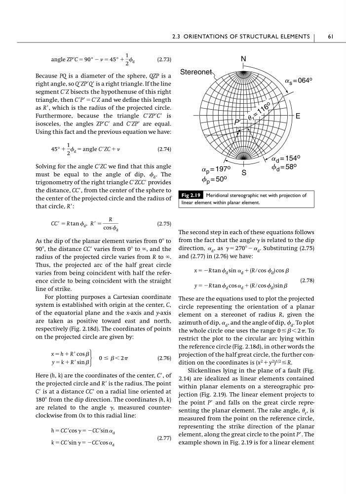
Slickenlines lying in the plane of a fault (Fig.
2.14) are idealized as linear elements contained
within planar elements on a stereographic projection (Fig. 2.19). The linear element projects to
the point PЈ and falls on the great circle representing the planar element. The rake angle, r , is
measured from the point on the reference circle,
representing the strike direction of the planar
element, along the great circle to the point PЈ. The
example shown in Fig. 2.19 is for a linear element
y ϭ ϪR tan d cos ␣ d ϩ (R ր cos d ) sin 
x ϭ ϪR tan d sin ␣ d ϩ (R ր cos d ) cos 
2.3 ORIENTATIONS OF STRUCTURAL ELEMENTS
61
Fig 2.19 Meridional stereographic net with projection of
linear element within planar element.
PЈ
N
E
S
Stereonet
a s = 064 o
u r = 1 1 6
o
a d = 154 o
f d = 58 o
a p = 197 o
f p = 50 o
Because PQ is a diameter of the sphere, QZP is a
right angle, so QЈZPЈQЈ is a right triangle. If the line
segment CЈZ bisects the hypothenuse of this right
triangle, then CЈPЈϭCЈZ and we define this length
as RЈ, which is the radius of the projected circle.
Furthermore, because the triangle CЈZPЈCЈ is
isosceles, the angles ZPЈCЈ and CЈZPЈ are equal.
Using this fact and the previous equation we have:
(2.74)
Solving for the angle CЈZC we find that this angle
must be equal to the angle of dip, d . The
trigonometry of the right triangle CЈZCCЈ provides
the distance, CCЈ, from the center of the sphere to
the center of the projected circle and the radius of
that circle, RЈ:
(2.75)
As the dip of the planar element varies from 0Њ to
90Њ, the distance CCЈ varies from 0Њ to ϱ, and the
radius of the projected circle varies from R to ϱ.
Thus, the projected arc of the half great circle
varies from being coincident with half the reference circle to being coincident with the straight
line of strike.
For plotting purposes a Cartesian coordinate
system is established with origin at the center, C,
of the equatorial plane and the x-axis and y-axis
are taken as positive toward east and north,
respectively (Fig. 2.18d). The coordinates of points
on the projected circle are given by:
(2.76)
Here (h, k) are the coordinates of the center, CЈ, of
the projected circle and RЈ is the radius. The point
CЈ is at a distance CCЈ on a radial line oriented at
180Њ from the dip direction. The coordinates (h, k)
are related to the angle ␥, measured counterclockwise from Ox to this radial line:
(2.77)
k ϭ CCЈ sin ␥ ϭ ϪCCЈ cos ␣ d
h ϭ CCЈ cos ␥ ϭ ϪCCЈ sin ␣ d
x ϭ h ϩ RЈ cos 
y ϭ k ϩ RЈ sin  ·
0 Յ  Ͻ 2
CCЈ ϭ R tan d , RЈ ϭ
R
cos d
45° ϩ
1
2
d ϭ angle CЈZC ϩ
angle ZPЈC ϭ 90° Ϫ ϭ 45° ϩ
1
2
d
The second step in each of these equations follows
from the fact that the angle ␥ is related to the dip
direction, ␣ d , as ␥ ϭ 270ЊϪ␣ d . Substituting (2.75)
and (2.77) in (2.76) we have:
(2.78)
These are the equations used to plot the projected
circle representing the orientation of a planar
element on a stereonet of radius R, given the
azimuth of dip, ␣ d , and the angle of dip, d . To plot
the whole circle one uses the range 0Յ  Ͻ 2. To
restrict the plot to the circular arc lying within
the reference circle (Fig. 2.18d), in other words the
projection of the half great circle, the further condition on the coordinates is (x
2 ϩ y
2 )
1/2 Յ R.
Slickenlines lying in the plane of a fault (Fig.
2.14) are idealized as linear elements contained
within planar elements on a stereographic projection (Fig. 2.19). The linear element projects to
the point PЈ and falls on the great circle representing the planar element. The rake angle, r , is
measured from the point on the reference circle,
representing the strike direction of the planar
element, along the great circle to the point PЈ. The
example shown in Fig. 2.19 is for a linear element
y ϭ ϪR tan d cos ␣ d ϩ (R ր cos d ) sin 
x ϭ ϪR tan d sin ␣ d ϩ (R ր cos d ) cos 
2.3 ORIENTATIONS OF STRUCTURAL ELEMENTS
61
Fig 2.19 Meridional stereographic net with projection of
linear element within planar element.
PЈ
N
E
S
Stereonet
a s = 064 o
u r = 1 1 6
o
a d = 154 o
f d = 58 o
a p = 197 o
f p = 50 o