

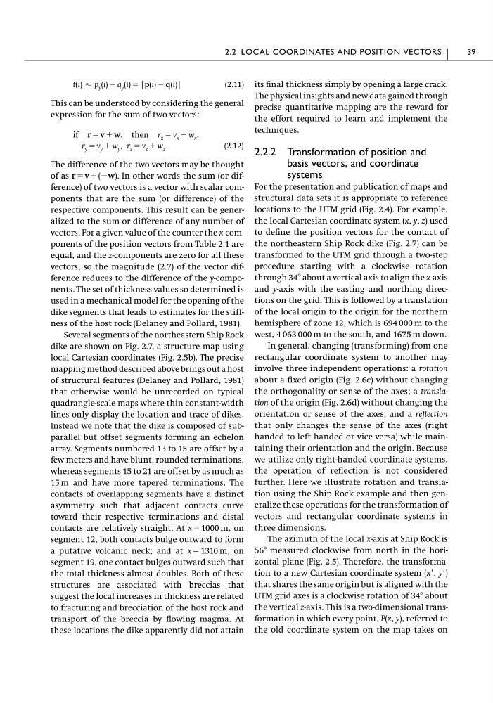
(2.11)
This can be understood by considering the general
expression for the sum of two vectors:
(2.12)
The difference of the two vectors may be thought
of as r ϭ v ϩ (Ϫw). In other words the sum (or difference) of two vectors is a vector with scalar components that are the sum (or difference) of the
respective components. This result can be generalized to the sum or difference of any number of
vectors. For a given value of the counter the x-components of the position vectors from Table 2.1 are
equal, and the z-components are zero for all these
vectors, so the magnitude (2.7) of the vector difference reduces to the difference of the y-components. The set of thickness values so determined is
used in a mechanical model for the opening of the
dike segments that leads to estimates for the stiffness of the host rock (Delaney and Pollard, 1981).
Several segments of the northeastern Ship Rock
dike are shown on Fig. 2.7, a structure map using
local Cartesian coordinates (Fig. 2.5b). The precise
mapping method described above brings out a host
of structural features (Delaney and Pollard, 1981)
that otherwise would be unrecorded on typical
quadrangle-scale maps where thin constant-width
lines only display the location and trace of dikes.
Instead we note that the dike is composed of subparallel but offset segments forming an echelon
array. Segments numbered 13 to 15 are offset by a
few meters and have blunt, rounded terminations,
whereas segments 15 to 21 are offset by as much as
15 m and have more tapered terminations. The
contacts of overlapping segments have a distinct
asymmetry such that adjacent contacts curve
toward their respective terminations and distal
contacts are relatively straight. At x ϭ 1000 m, on
segment 12, both contacts bulge outward to form
a putative volcanic neck; and at x ϭ 1310 m, on
segment 19, one contact bulges outward such that
the total thickness almost doubles. Both of these
structures are associated with breccias that
suggest the local increases in thickness are related
to fracturing and brecciation of the host rock and
transport of the breccia by flowing magma. At
these locations the dike apparently did not attain
r z ϭ v z ϩ w z
r y ϭ v y ϩ w y ,
if r ϭ v ϩ w, then r x ϭ v x ϩ w x ,
t(i) Ϸ p y (i) Ϫ q y (i) ϭ |p(i) Ϫ q(i)|
its final thickness simply by opening a large crack.
The physical insights and new data gained through
precise quantitative mapping are the reward for
the effort required to learn and implement the
techniques.
2.2.2 Transformation of position and
basis vectors, and coordinate
systems
For the presentation and publication of maps and
structural data sets it is appropriate to reference
locations to the UTM grid (Fig. 2.4). For example,
the local Cartesian coordinate system (x, y, z) used
to define the position vectors for the contact of
the northeastern Ship Rock dike (Fig. 2.7) can be
transformed to the UTM grid through a two-step
procedure starting with a clockwise rotation
through 34Њ about a vertical axis to align the x-axis
and y-axis with the easting and northing directions on the grid. This is followed by a translation
of the local origin to the origin for the northern
hemisphere of zone 12, which is 694 000 m to the
west, 4 063 000 m to the south, and 1675 m down.
In general, changing (transforming) from one
rectangular coordinate system to another may
involve three independent operations: a rotation
about a fixed origin (Fig. 2.6c) without changing
the orthogonality or sense of the axes; a translation of the origin (Fig. 2.6d) without changing the
orientation or sense of the axes; and a reflection
that only changes the sense of the axes (right
handed to left handed or vice versa) while maintaining their orientation and the origin. Because
we utilize only right-handed coordinate systems,
the operation of reflection is not considered
further. Here we illustrate rotation and translation using the Ship Rock example and then generalize these operations for the transformation of
vectors and rectangular coordinate systems in
three dimensions.
The azimuth of the local x-axis at Ship Rock is
56Њ measured clockwise from north in the horizontal plane (Fig. 2.5). Therefore, the transformation to a new Cartesian coordinate system (xЈ, yЈ)
that shares the same origin but is aligned with the
UTM grid axes is a clockwise rotation of 34Њ about
the vertical z-axis. This is a two-dimensional transformation in which every point, P(x, y), referred to
the old coordinate system on the map takes on
2.2 LOCAL COORDINATES AND POSITION VECTORS
39
This can be understood by considering the general
expression for the sum of two vectors:
(2.12)
The difference of the two vectors may be thought
of as r ϭ v ϩ (Ϫw). In other words the sum (or difference) of two vectors is a vector with scalar components that are the sum (or difference) of the
respective components. This result can be generalized to the sum or difference of any number of
vectors. For a given value of the counter the x-components of the position vectors from Table 2.1 are
equal, and the z-components are zero for all these
vectors, so the magnitude (2.7) of the vector difference reduces to the difference of the y-components. The set of thickness values so determined is
used in a mechanical model for the opening of the
dike segments that leads to estimates for the stiffness of the host rock (Delaney and Pollard, 1981).
Several segments of the northeastern Ship Rock
dike are shown on Fig. 2.7, a structure map using
local Cartesian coordinates (Fig. 2.5b). The precise
mapping method described above brings out a host
of structural features (Delaney and Pollard, 1981)
that otherwise would be unrecorded on typical
quadrangle-scale maps where thin constant-width
lines only display the location and trace of dikes.
Instead we note that the dike is composed of subparallel but offset segments forming an echelon
array. Segments numbered 13 to 15 are offset by a
few meters and have blunt, rounded terminations,
whereas segments 15 to 21 are offset by as much as
15 m and have more tapered terminations. The
contacts of overlapping segments have a distinct
asymmetry such that adjacent contacts curve
toward their respective terminations and distal
contacts are relatively straight. At x ϭ 1000 m, on
segment 12, both contacts bulge outward to form
a putative volcanic neck; and at x ϭ 1310 m, on
segment 19, one contact bulges outward such that
the total thickness almost doubles. Both of these
structures are associated with breccias that
suggest the local increases in thickness are related
to fracturing and brecciation of the host rock and
transport of the breccia by flowing magma. At
these locations the dike apparently did not attain
r z ϭ v z ϩ w z
r y ϭ v y ϩ w y ,
if r ϭ v ϩ w, then r x ϭ v x ϩ w x ,
t(i) Ϸ p y (i) Ϫ q y (i) ϭ |p(i) Ϫ q(i)|
its final thickness simply by opening a large crack.
The physical insights and new data gained through
precise quantitative mapping are the reward for
the effort required to learn and implement the
techniques.
2.2.2 Transformation of position and
basis vectors, and coordinate
systems
For the presentation and publication of maps and
structural data sets it is appropriate to reference
locations to the UTM grid (Fig. 2.4). For example,
the local Cartesian coordinate system (x, y, z) used
to define the position vectors for the contact of
the northeastern Ship Rock dike (Fig. 2.7) can be
transformed to the UTM grid through a two-step
procedure starting with a clockwise rotation
through 34Њ about a vertical axis to align the x-axis
and y-axis with the easting and northing directions on the grid. This is followed by a translation
of the local origin to the origin for the northern
hemisphere of zone 12, which is 694 000 m to the
west, 4 063 000 m to the south, and 1675 m down.
In general, changing (transforming) from one
rectangular coordinate system to another may
involve three independent operations: a rotation
about a fixed origin (Fig. 2.6c) without changing
the orthogonality or sense of the axes; a translation of the origin (Fig. 2.6d) without changing the
orientation or sense of the axes; and a reflection
that only changes the sense of the axes (right
handed to left handed or vice versa) while maintaining their orientation and the origin. Because
we utilize only right-handed coordinate systems,
the operation of reflection is not considered
further. Here we illustrate rotation and translation using the Ship Rock example and then generalize these operations for the transformation of
vectors and rectangular coordinate systems in
three dimensions.
The azimuth of the local x-axis at Ship Rock is
56Њ measured clockwise from north in the horizontal plane (Fig. 2.5). Therefore, the transformation to a new Cartesian coordinate system (xЈ, yЈ)
that shares the same origin but is aligned with the
UTM grid axes is a clockwise rotation of 34Њ about
the vertical z-axis. This is a two-dimensional transformation in which every point, P(x, y), referred to
the old coordinate system on the map takes on
2.2 LOCAL COORDINATES AND POSITION VECTORS
39