

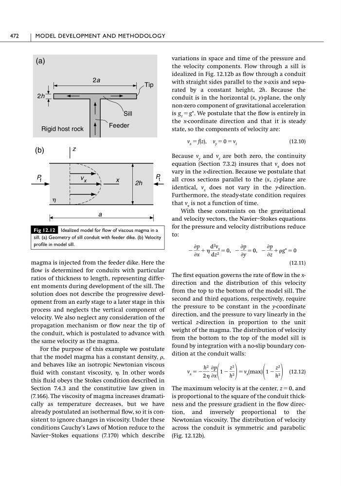
magma is injected from the feeder dike. Here the
flow is determined for conduits with particular
ratios of thickness to length, representing different moments during development of the sill. The
solution does not describe the progressive development from an early stage to a later stage in this
process and neglects the vertical component of
velocity. We also neglect any consideration of the
propagation mechanism or flow near the tip of
the conduit, which is postulated to advance with
the same velocity as the magma.
For the purpose of this example we postulate
that the model magma has a constant density, ,
and behaves like an isotropic Newtonian viscous
fluid with constant viscosity, . In other words
this fluid obeys the Stokes condition described in
Section 7.4.3 and the constitutive law given in
(7.166). The viscosity of magma increases dramatically as temperature decreases, but we have
already postulated an isothermal flow, so it is consistent to ignore changes in viscosity. Under these
conditions Cauchy’s Laws of Motion reduce to the
Navier–Stokes equations (7.170) which describe
variations in space and time of the pressure and
the velocity components. Flow through a sill is
idealized in Fig. 12.12b as flow through a conduit
with straight sides parallel to the x-axis and separated by a constant height, 2h. Because the
conduit is in the horizontal (x, y)-plane, the only
non-zero component of gravitational acceleration
is g z ϭ g*. We postulate that the flow is entirely in
the x-coordinate direction and that it is steady
state, so the components of velocity are:
(12.10)
Because v y and v z are both zero, the continuity
equation (Section 7.3.2) insures that v x does not
vary in the x-direction. Because we postulate that
all cross sections parallel to the (x, z)-plane are
identical, v x does not vary in the y-direction.
Furthermore, the steady-state condition requires
that v x is not a function of time.
With these constraints on the gravitational
and velocity vectors, the Navier–Stokes equations
for the pressure and velocity distributions reduce
to:
(12.11)
The first equation governs the rate of flow in the xdirection and the distribution of this velocity
from the top to the bottom of the model sill. The
second and third equations, respectively, require
the pressure to be constant in the y-coordinate
direction, and the pressure to vary linearly in the
vertical z-direction in proportion to the unit
weight of the magma. The distribution of velocity
from the bottom to the top of the model sill is
found by integration with a no-slip boundary condition at the conduit walls:
(12.12)
The maximum velocity is at the center, z ϭ 0, and
is proportional to the square of the conduit thickness and the pressure gradient in the flow direction, and inversely proportional to the
Newtonian viscosity. The distribution of velocity
across the conduit is symmetric and parabolic
(Fig. 12.12b).
v x ϭ Ϫ
h 2
2
Ѩp
Ѩx 1 Ϫ
z 2
h 2 ϭ v x (max) 1 Ϫ
z 2
h 2
Ϫ
Ѩp
Ѩx
ϩ
d 2 v x
dz 2 ϭ 0, Ϫ
Ѩp
Ѩy
ϭ 0, Ϫ
Ѩp
Ѩz
ϩ g* ϭ 0
v x ϭ f(z), v y ϭ 0 ϭ v z
472
MODEL DEVELOPMENT AND METHODOLOGY
Fig 12.12 Idealized model for flow of viscous magma in a
sill. (a) Geometry of sill conduit with feeder dike. (b) Velocity
profile in model sill.
z
(b)
2a
(a)
Sill
2h
P t
Tip
Feeder
P f
a
v x
h
x
Rigid host rock
2h
flow is determined for conduits with particular
ratios of thickness to length, representing different moments during development of the sill. The
solution does not describe the progressive development from an early stage to a later stage in this
process and neglects the vertical component of
velocity. We also neglect any consideration of the
propagation mechanism or flow near the tip of
the conduit, which is postulated to advance with
the same velocity as the magma.
For the purpose of this example we postulate
that the model magma has a constant density, ,
and behaves like an isotropic Newtonian viscous
fluid with constant viscosity, . In other words
this fluid obeys the Stokes condition described in
Section 7.4.3 and the constitutive law given in
(7.166). The viscosity of magma increases dramatically as temperature decreases, but we have
already postulated an isothermal flow, so it is consistent to ignore changes in viscosity. Under these
conditions Cauchy’s Laws of Motion reduce to the
Navier–Stokes equations (7.170) which describe
variations in space and time of the pressure and
the velocity components. Flow through a sill is
idealized in Fig. 12.12b as flow through a conduit
with straight sides parallel to the x-axis and separated by a constant height, 2h. Because the
conduit is in the horizontal (x, y)-plane, the only
non-zero component of gravitational acceleration
is g z ϭ g*. We postulate that the flow is entirely in
the x-coordinate direction and that it is steady
state, so the components of velocity are:
(12.10)
Because v y and v z are both zero, the continuity
equation (Section 7.3.2) insures that v x does not
vary in the x-direction. Because we postulate that
all cross sections parallel to the (x, z)-plane are
identical, v x does not vary in the y-direction.
Furthermore, the steady-state condition requires
that v x is not a function of time.
With these constraints on the gravitational
and velocity vectors, the Navier–Stokes equations
for the pressure and velocity distributions reduce
to:
(12.11)
The first equation governs the rate of flow in the xdirection and the distribution of this velocity
from the top to the bottom of the model sill. The
second and third equations, respectively, require
the pressure to be constant in the y-coordinate
direction, and the pressure to vary linearly in the
vertical z-direction in proportion to the unit
weight of the magma. The distribution of velocity
from the bottom to the top of the model sill is
found by integration with a no-slip boundary condition at the conduit walls:
(12.12)
The maximum velocity is at the center, z ϭ 0, and
is proportional to the square of the conduit thickness and the pressure gradient in the flow direction, and inversely proportional to the
Newtonian viscosity. The distribution of velocity
across the conduit is symmetric and parabolic
(Fig. 12.12b).
v x ϭ Ϫ
h 2
2
Ѩp
Ѩx 1 Ϫ
z 2
h 2 ϭ v x (max) 1 Ϫ
z 2
h 2
Ϫ
Ѩp
Ѩx
ϩ
d 2 v x
dz 2 ϭ 0, Ϫ
Ѩp
Ѩy
ϭ 0, Ϫ
Ѩp
Ѩz
ϩ g* ϭ 0
v x ϭ f(z), v y ϭ 0 ϭ v z
472
MODEL DEVELOPMENT AND METHODOLOGY
Fig 12.12 Idealized model for flow of viscous magma in a
sill. (a) Geometry of sill conduit with feeder dike. (b) Velocity
profile in model sill.
z
(b)
2a
(a)
Sill
2h
P t
Tip
Feeder
P f
a
v x
h
x
Rigid host rock
2h