

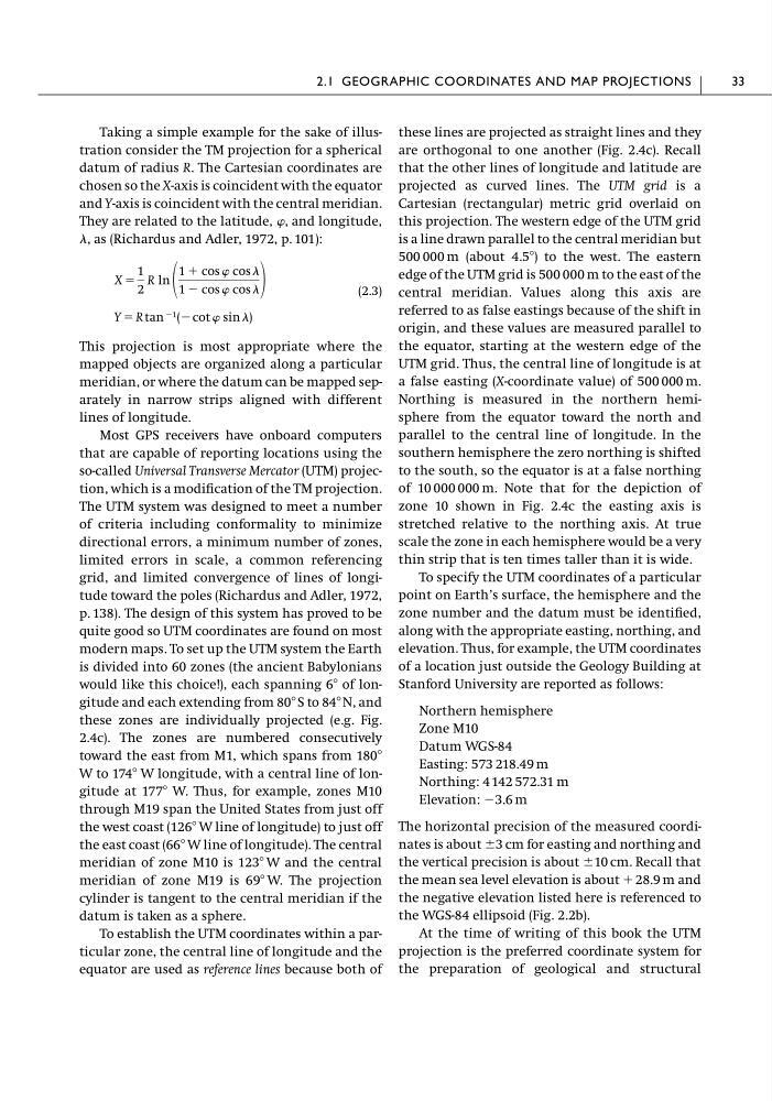
Taking a simple example for the sake of illustration consider the TM projection for a spherical
datum of radius R. The Cartesian coordinates are
chosen so the X-axis is coincident with the equator
and Y-axis is coincident with the central meridian.
They are related to the latitude, , and longitude,
, as (Richardus and Adler, 1972, p. 101):
(2.3)
This projection is most appropriate where the
mapped objects are organized along a particular
meridian, or where the datum can be mapped separately in narrow strips aligned with different
lines of longitude.
Most GPS receivers have onboard computers
that are capable of reporting locations using the
so-called Universal Transverse Mercator (UTM) projection, which is a modification of the TM projection.
The UTM system was designed to meet a number
of criteria including conformality to minimize
directional errors, a minimum number of zones,
limited errors in scale, a common referencing
grid, and limited convergence of lines of longitude toward the poles (Richardus and Adler, 1972,
p. 138). The design of this system has proved to be
quite good so UTM coordinates are found on most
modern maps. To set up the UTM system the Earth
is divided into 60 zones (the ancient Babylonians
would like this choice!), each spanning 6Њ of longitude and each extending from 80Њ S to 84Њ N, and
these zones are individually projected (e.g. Fig.
2.4c). The zones are numbered consecutively
toward the east from M1, which spans from 180Њ
W to 174Њ W longitude, with a central line of longitude at 177Њ W. Thus, for example, zones M10
through M19 span the United States from just off
the west coast (126Њ W line of longitude) to just off
the east coast (66Њ W line of longitude). The central
meridian of zone M10 is 123Њ W and the central
meridian of zone M19 is 69Њ W. The projection
cylinder is tangent to the central meridian if the
datum is taken as a sphere.
To establish the UTM coordinates within a particular zone, the central line of longitude and the
equator are used as reference lines because both of
Y ϭ R tan Ϫ1 (Ϫ cot sin )
X ϭ
1
2
R ln
1 ϩ cos cos
1 Ϫ cos cos
these lines are projected as straight lines and they
are orthogonal to one another (Fig. 2.4c). Recall
that the other lines of longitude and latitude are
projected as curved lines. The UTM grid is a
Cartesian (rectangular) metric grid overlaid on
this projection. The western edge of the UTM grid
is a line drawn parallel to the central meridian but
500 000 m (about 4.5Њ) to the west. The eastern
edge of the UTM grid is 500 000 m to the east of the
central meridian. Values along this axis are
referred to as false eastings because of the shift in
origin, and these values are measured parallel to
the equator, starting at the western edge of the
UTM grid. Thus, the central line of longitude is at
a false easting (X-coordinate value) of 500 000 m.
Northing is measured in the northern hemisphere from the equator toward the north and
parallel to the central line of longitude. In the
southern hemisphere the zero northing is shifted
to the south, so the equator is at a false northing
of 10 000 000 m. Note that for the depiction of
zone 10 shown in Fig. 2.4c the easting axis is
stretched relative to the northing axis. At true
scale the zone in each hemisphere would be a very
thin strip that is ten times taller than it is wide.
To specify the UTM coordinates of a particular
point on Earth’s surface, the hemisphere and the
zone number and the datum must be identified,
along with the appropriate easting, northing, and
elevation. Thus, for example, the UTM coordinates
of a location just outside the Geology Building at
Stanford University are reported as follows:
Northern hemisphere
Zone M10
Datum WGS-84
Easting: 573 218.49 m
Northing: 4 142 572.31 m
Elevation: Ϫ3.6 m
The horizontal precision of the measured coordinates is about Ϯ3 cm for easting and northing and
the vertical precision is about Ϯ10 cm. Recall that
the mean sea level elevation is about ϩ 28.9 m and
the negative elevation listed here is referenced to
the WGS-84 ellipsoid (Fig. 2.2b).
At the time of writing of this book the UTM
projection is the preferred coordinate system for
the preparation of geological and structural
2.1 GEOGRAPHIC COORDINATES AND MAP PROJECTIONS
33
datum of radius R. The Cartesian coordinates are
chosen so the X-axis is coincident with the equator
and Y-axis is coincident with the central meridian.
They are related to the latitude, , and longitude,
, as (Richardus and Adler, 1972, p. 101):
(2.3)
This projection is most appropriate where the
mapped objects are organized along a particular
meridian, or where the datum can be mapped separately in narrow strips aligned with different
lines of longitude.
Most GPS receivers have onboard computers
that are capable of reporting locations using the
so-called Universal Transverse Mercator (UTM) projection, which is a modification of the TM projection.
The UTM system was designed to meet a number
of criteria including conformality to minimize
directional errors, a minimum number of zones,
limited errors in scale, a common referencing
grid, and limited convergence of lines of longitude toward the poles (Richardus and Adler, 1972,
p. 138). The design of this system has proved to be
quite good so UTM coordinates are found on most
modern maps. To set up the UTM system the Earth
is divided into 60 zones (the ancient Babylonians
would like this choice!), each spanning 6Њ of longitude and each extending from 80Њ S to 84Њ N, and
these zones are individually projected (e.g. Fig.
2.4c). The zones are numbered consecutively
toward the east from M1, which spans from 180Њ
W to 174Њ W longitude, with a central line of longitude at 177Њ W. Thus, for example, zones M10
through M19 span the United States from just off
the west coast (126Њ W line of longitude) to just off
the east coast (66Њ W line of longitude). The central
meridian of zone M10 is 123Њ W and the central
meridian of zone M19 is 69Њ W. The projection
cylinder is tangent to the central meridian if the
datum is taken as a sphere.
To establish the UTM coordinates within a particular zone, the central line of longitude and the
equator are used as reference lines because both of
Y ϭ R tan Ϫ1 (Ϫ cot sin )
X ϭ
1
2
R ln
1 ϩ cos cos
1 Ϫ cos cos
these lines are projected as straight lines and they
are orthogonal to one another (Fig. 2.4c). Recall
that the other lines of longitude and latitude are
projected as curved lines. The UTM grid is a
Cartesian (rectangular) metric grid overlaid on
this projection. The western edge of the UTM grid
is a line drawn parallel to the central meridian but
500 000 m (about 4.5Њ) to the west. The eastern
edge of the UTM grid is 500 000 m to the east of the
central meridian. Values along this axis are
referred to as false eastings because of the shift in
origin, and these values are measured parallel to
the equator, starting at the western edge of the
UTM grid. Thus, the central line of longitude is at
a false easting (X-coordinate value) of 500 000 m.
Northing is measured in the northern hemisphere from the equator toward the north and
parallel to the central line of longitude. In the
southern hemisphere the zero northing is shifted
to the south, so the equator is at a false northing
of 10 000 000 m. Note that for the depiction of
zone 10 shown in Fig. 2.4c the easting axis is
stretched relative to the northing axis. At true
scale the zone in each hemisphere would be a very
thin strip that is ten times taller than it is wide.
To specify the UTM coordinates of a particular
point on Earth’s surface, the hemisphere and the
zone number and the datum must be identified,
along with the appropriate easting, northing, and
elevation. Thus, for example, the UTM coordinates
of a location just outside the Geology Building at
Stanford University are reported as follows:
Northern hemisphere
Zone M10
Datum WGS-84
Easting: 573 218.49 m
Northing: 4 142 572.31 m
Elevation: Ϫ3.6 m
The horizontal precision of the measured coordinates is about Ϯ3 cm for easting and northing and
the vertical precision is about Ϯ10 cm. Recall that
the mean sea level elevation is about ϩ 28.9 m and
the negative elevation listed here is referenced to
the WGS-84 ellipsoid (Fig. 2.2b).
At the time of writing of this book the UTM
projection is the preferred coordinate system for
the preparation of geological and structural
2.1 GEOGRAPHIC COORDINATES AND MAP PROJECTIONS
33