

In the absence of basic-state transport, the condition of zero normal flux at the interface, to first
order in slope A, is:
(11.88)
To the present approximation, this yields the condition:
(11.89)
The five equations obtained by combining
(11.87) and (11.89) are solved numerically for the
constants a, b, c 1 , d 1 , and g 1 . The added complexity
relative to the necking problem considered above
suggests that closed-form results may be laborious
to obtain and may not easily provide physical
insight. We do not attempt this here.
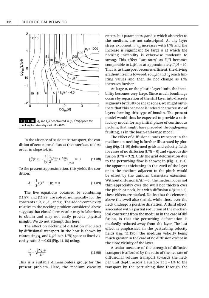
The effect on necking of dilatation mediated
by diffusional transport in the host is shown by
contouring q d and L d /H in (n, L*/H)-space at fixed viscosity ratio R ϭ 0.05 (Fig. 11.18) using:
(11.90)
This is a suitable dimensionless group for the
present problem. Here, the medium viscosity
L*
H
ϭ
√
2 1
H 2
d 1 Ϫ
1
2
( 2 Ϫ 1)g 1 ϭ 0
J
~(1)
y (x, 0) ϳ
Ѩ
Ѩy ΄
1
2
( ~ (1)
xx ϩ
~ (1)
xx ) ΅ (x,0)
Х 0
enters, but parameters and , which also refer to
the medium, are not subscripted. At any layer
stress exponent, n, q d increases with L*/H and the
increase is significant for large n at which the
necking instability is otherwise moderate to
strong. This effect “saturates” as L*/H becomes
comparable to L d /H, or at approximately L*/Hϭ10.
That is, as transport becomes efficient, the driving
gradient itself is lowered, so L d /H and q d reach limiting values and then do not change as L*/H
increases further.
At large n, or the plastic layer limit, the instability becomes very large. Since much boudinage
occurs by separation of the stiff layer into discrete
segments by faults or shear zones, we might anticipate that this behavior is indeed characteristic of
layers forming this type of boudin. The present
model would thus be expected to provide a satisfactory model for any initial phase of continuous
necking that might have preceded through-going
faulting, as in the basin-and-range model.
The effect of diffusional mass transport in the
medium on necking is further illustrated by plotting (Fig. 11.19) deformed grids and velocity fields
for cases of no diffusion (L*/H ϭ 0) and vigorous diffusion (L*/H ϭ 3.2). Only the grid deformation due
to the perturbing flow is shown; in (Fig. 11.19a),
the apparent thickening in the swell of the layer
or in the medium adjacent to the pinch would
be offset by the uniform basic-state extension.
Without diffusion (L*/H ϭ 0), the medium does not
thin appreciably over the swell nor thicken over
the pinch or neck, but with diffusion (L*/H ϭ 3.2),
these effects are marked. Notice that the elements
above the swell also shrink, while those over the
neck undergo a positive dilatation. A third effect,
associated with a partial reduction of the mechanical constraint from the medium in the case of diffusion, is that the perturbing deformation is
markedly reduced away from the layer. The last
effect is emphasized in the perturbing velocity
fields (Fig. 11.19b); the medium velocity being
much greater in the case of no diffusion except in
the close vicinity of the layer.
A scalar measure of the strength of diffusive
transport is afforded by the ratio of the net rate of
diffusional volume transport towards the neck
per unit depth across a surface at x ϭ L/4 to the
transport by the perturbing flow through the
444
RHEOLOGICAL BEHAVIOR
Fig 11.18 q d and L d /H contoured in (n, L
* /H)-space for
necking for viscosity ratio R ϭ0.05.
0
1
2
3
4
–2
–1
0
1
2
5
10 20 40
100
200
400
3.5
4
5
6
8
10
10
12
log 10 (n)
log
10 (L*/H)
q d = 1000
L d /H = 4.5
10
order in slope A, is:
(11.88)
To the present approximation, this yields the condition:
(11.89)
The five equations obtained by combining
(11.87) and (11.89) are solved numerically for the
constants a, b, c 1 , d 1 , and g 1 . The added complexity
relative to the necking problem considered above
suggests that closed-form results may be laborious
to obtain and may not easily provide physical
insight. We do not attempt this here.
The effect on necking of dilatation mediated
by diffusional transport in the host is shown by
contouring q d and L d /H in (n, L*/H)-space at fixed viscosity ratio R ϭ 0.05 (Fig. 11.18) using:
(11.90)
This is a suitable dimensionless group for the
present problem. Here, the medium viscosity
L*
H
ϭ
√
2 1
H 2
d 1 Ϫ
1
2
( 2 Ϫ 1)g 1 ϭ 0
J
~(1)
y (x, 0) ϳ
Ѩ
Ѩy ΄
1
2
( ~ (1)
xx ϩ
~ (1)
xx ) ΅ (x,0)
Х 0
enters, but parameters and , which also refer to
the medium, are not subscripted. At any layer
stress exponent, n, q d increases with L*/H and the
increase is significant for large n at which the
necking instability is otherwise moderate to
strong. This effect “saturates” as L*/H becomes
comparable to L d /H, or at approximately L*/Hϭ10.
That is, as transport becomes efficient, the driving
gradient itself is lowered, so L d /H and q d reach limiting values and then do not change as L*/H
increases further.
At large n, or the plastic layer limit, the instability becomes very large. Since much boudinage
occurs by separation of the stiff layer into discrete
segments by faults or shear zones, we might anticipate that this behavior is indeed characteristic of
layers forming this type of boudin. The present
model would thus be expected to provide a satisfactory model for any initial phase of continuous
necking that might have preceded through-going
faulting, as in the basin-and-range model.
The effect of diffusional mass transport in the
medium on necking is further illustrated by plotting (Fig. 11.19) deformed grids and velocity fields
for cases of no diffusion (L*/H ϭ 0) and vigorous diffusion (L*/H ϭ 3.2). Only the grid deformation due
to the perturbing flow is shown; in (Fig. 11.19a),
the apparent thickening in the swell of the layer
or in the medium adjacent to the pinch would
be offset by the uniform basic-state extension.
Without diffusion (L*/H ϭ 0), the medium does not
thin appreciably over the swell nor thicken over
the pinch or neck, but with diffusion (L*/H ϭ 3.2),
these effects are marked. Notice that the elements
above the swell also shrink, while those over the
neck undergo a positive dilatation. A third effect,
associated with a partial reduction of the mechanical constraint from the medium in the case of diffusion, is that the perturbing deformation is
markedly reduced away from the layer. The last
effect is emphasized in the perturbing velocity
fields (Fig. 11.19b); the medium velocity being
much greater in the case of no diffusion except in
the close vicinity of the layer.
A scalar measure of the strength of diffusive
transport is afforded by the ratio of the net rate of
diffusional volume transport towards the neck
per unit depth across a surface at x ϭ L/4 to the
transport by the perturbing flow through the
444
RHEOLOGICAL BEHAVIOR
Fig 11.18 q d and L d /H contoured in (n, L
* /H)-space for
necking for viscosity ratio R ϭ0.05.
0
1
2
3
4
–2
–1
0
1
2
5
10 20 40
100
200
400
3.5
4
5
6
8
10
10
12
log 10 (n)
log
10 (L*/H)
q d = 1000
L d /H = 4.5
10