

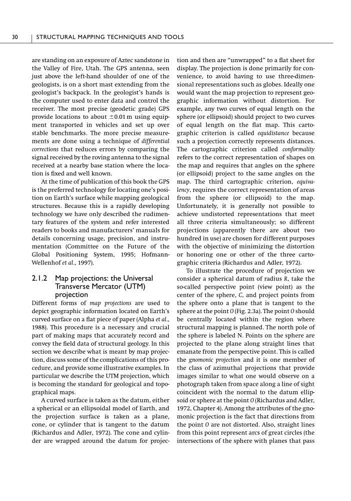
are standing on an exposure of Aztec sandstone in
the Valley of Fire, Utah. The GPS antenna, seen
just above the left-hand shoulder of one of the
geologists, is on a short mast extending from the
geologist’s backpack. In the geologist’s hands is
the computer used to enter data and control the
receiver. The most precise (geodetic grade) GPS
provide locations to about Ϯ0.01 m using equipment transported in vehicles and set up over
stable benchmarks. The more precise measurements are done using a technique of differential
corrections that reduces errors by comparing the
signal received by the roving antenna to the signal
received at a nearby base station where the location is fixed and well known.
At the time of publication of this book the GPS
is the preferred technology for locating one’s position on Earth’s surface while mapping geological
structures. Because this is a rapidly developing
technology we have only described the rudimentary features of the system and refer interested
readers to books and manufacturers’ manuals for
details concerning usage, precision, and instrumentation (Committee on the Future of the
Global Positioning System, 1995; HofmannWellenhof et al., 1997).
2.1.2 Map projections: the Universal
Transverse Mercator (UTM)
projection
Different forms of map projections are used to
depict geographic information located on Earth’s
curved surface on a flat piece of paper (Alpha et al.,
1988). This procedure is a necessary and crucial
part of making maps that accurately record and
convey the field data of structural geology. In this
section we describe what is meant by map projection, discuss some of the complications of this procedure, and provide some illustrative examples. In
particular we describe the UTM projection, which
is becoming the standard for geological and topographical maps.
A curved surface is taken as the datum, either
a spherical or an ellipsoidal model of Earth, and
the projection surface is taken as a plane,
cone, or cylinder that is tangent to the datum
(Richardus and Adler, 1972). The cone and cylinder are wrapped around the datum for projection and then are “unwrapped” to a flat sheet for
display. The projection is done primarily for convenience, to avoid having to use three-dimensional representations such as globes. Ideally one
would want the map projection to represent geographic information without distortion. For
example, any two curves of equal length on the
sphere (or ellipsoid) should project to two curves
of equal length on the flat map. This cartographic criterion is called equidistance because
such a projection correctly represents distances.
The cartographic criterion called conformality
refers to the correct representation of shapes on
the map and requires that angles on the sphere
(or ellipsoid) project to the same angles on the
map. The third cartographic criterion, equivalency, requires the correct representation of areas
from the sphere (or ellipsoid) to the map.
Unfortunately, it is generally not possible to
achieve undistorted representations that meet
all three criteria simultaneously; so different
projections (apparently there are about two
hundred in use) are chosen for different purposes
with the objective of minimizing the distortion
or honoring one or other of the three cartographic criteria (Richardus and Adler, 1972).
To illustrate the procedure of projection we
consider a spherical datum of radius R, take the
so-called perspective point (view point) as the
center of the sphere, C, and project points from
the sphere onto a plane that is tangent to the
sphere at the point O (Fig. 2.3a). The point O should
be centrally located within the region where
structural mapping is planned. The north pole of
the sphere is labeled N. Points on the sphere are
projected to the plane along straight lines that
emanate from the perspective point. This is called
the gnomonic projection and it is one member of
the class of azimuthal projections that provide
images similar to what one would observe on a
photograph taken from space along a line of sight
coincident with the normal to the datum ellipsoid or sphere at the point O (Richardus and Adler,
1972, Chapter 4). Among the attributes of the gnomonic projection is the fact that directions from
the point O are not distorted. Also, straight lines
from this point represent arcs of great circles (the
intersections of the sphere with planes that pass
30
STRUCTURAL MAPPING TECHNIQUES AND TOOLS
the Valley of Fire, Utah. The GPS antenna, seen
just above the left-hand shoulder of one of the
geologists, is on a short mast extending from the
geologist’s backpack. In the geologist’s hands is
the computer used to enter data and control the
receiver. The most precise (geodetic grade) GPS
provide locations to about Ϯ0.01 m using equipment transported in vehicles and set up over
stable benchmarks. The more precise measurements are done using a technique of differential
corrections that reduces errors by comparing the
signal received by the roving antenna to the signal
received at a nearby base station where the location is fixed and well known.
At the time of publication of this book the GPS
is the preferred technology for locating one’s position on Earth’s surface while mapping geological
structures. Because this is a rapidly developing
technology we have only described the rudimentary features of the system and refer interested
readers to books and manufacturers’ manuals for
details concerning usage, precision, and instrumentation (Committee on the Future of the
Global Positioning System, 1995; HofmannWellenhof et al., 1997).
2.1.2 Map projections: the Universal
Transverse Mercator (UTM)
projection
Different forms of map projections are used to
depict geographic information located on Earth’s
curved surface on a flat piece of paper (Alpha et al.,
1988). This procedure is a necessary and crucial
part of making maps that accurately record and
convey the field data of structural geology. In this
section we describe what is meant by map projection, discuss some of the complications of this procedure, and provide some illustrative examples. In
particular we describe the UTM projection, which
is becoming the standard for geological and topographical maps.
A curved surface is taken as the datum, either
a spherical or an ellipsoidal model of Earth, and
the projection surface is taken as a plane,
cone, or cylinder that is tangent to the datum
(Richardus and Adler, 1972). The cone and cylinder are wrapped around the datum for projection and then are “unwrapped” to a flat sheet for
display. The projection is done primarily for convenience, to avoid having to use three-dimensional representations such as globes. Ideally one
would want the map projection to represent geographic information without distortion. For
example, any two curves of equal length on the
sphere (or ellipsoid) should project to two curves
of equal length on the flat map. This cartographic criterion is called equidistance because
such a projection correctly represents distances.
The cartographic criterion called conformality
refers to the correct representation of shapes on
the map and requires that angles on the sphere
(or ellipsoid) project to the same angles on the
map. The third cartographic criterion, equivalency, requires the correct representation of areas
from the sphere (or ellipsoid) to the map.
Unfortunately, it is generally not possible to
achieve undistorted representations that meet
all three criteria simultaneously; so different
projections (apparently there are about two
hundred in use) are chosen for different purposes
with the objective of minimizing the distortion
or honoring one or other of the three cartographic criteria (Richardus and Adler, 1972).
To illustrate the procedure of projection we
consider a spherical datum of radius R, take the
so-called perspective point (view point) as the
center of the sphere, C, and project points from
the sphere onto a plane that is tangent to the
sphere at the point O (Fig. 2.3a). The point O should
be centrally located within the region where
structural mapping is planned. The north pole of
the sphere is labeled N. Points on the sphere are
projected to the plane along straight lines that
emanate from the perspective point. This is called
the gnomonic projection and it is one member of
the class of azimuthal projections that provide
images similar to what one would observe on a
photograph taken from space along a line of sight
coincident with the normal to the datum ellipsoid or sphere at the point O (Richardus and Adler,
1972, Chapter 4). Among the attributes of the gnomonic projection is the fact that directions from
the point O are not distorted. Also, straight lines
from this point represent arcs of great circles (the
intersections of the sphere with planes that pass
30
STRUCTURAL MAPPING TECHNIQUES AND TOOLS