

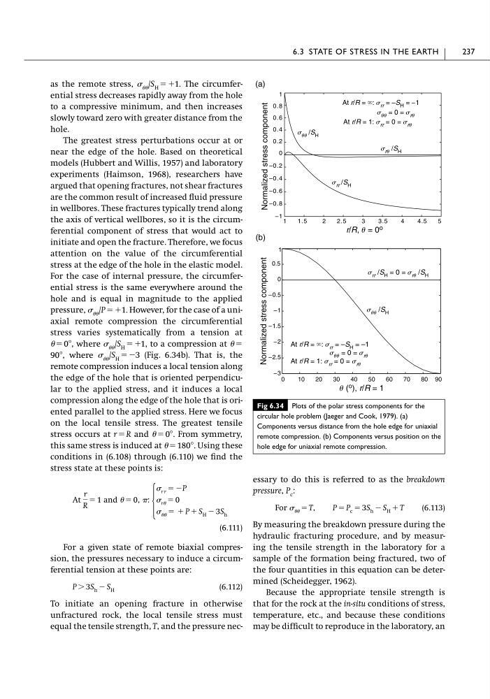
as the remote stress, /S H ϭϩ1. The circumferential stress decreases rapidly away from the hole
to a compressive minimum, and then increases
slowly toward zero with greater distance from the
hole.
The greatest stress perturbations occur at or
near the edge of the hole. Based on theoretical
models (Hubbert and Willis, 1957) and laboratory
experiments (Haimson, 1968), researchers have
argued that opening fractures, not shear fractures
are the common result of increased fluid pressure
in wellbores. These fractures typically trend along
the axis of vertical wellbores, so it is the circumferential component of stress that would act to
initiate and open the fracture. Therefore, we focus
attention on the value of the circumferential
stress at the edge of the hole in the elastic model.
For the case of internal pressure, the circumferential stress is the same everywhere around the
hole and is equal in magnitude to the applied
pressure, /P ϭϩ1. However, for the case of a uniaxial remote compression the circumferential
stress varies systematically from a tension at
ϭ 0Њ, where /S H ϭϩ1, to a compression at ϭ
90Њ, where /S H ϭϪ3 (Fig. 6.34b). That is, the
remote compression induces a local tension along
the edge of the hole that is oriented perpendicular to the applied stress, and it induces a local
compression along the edge of the hole that is oriented parallel to the applied stress. Here we focus
on the local tensile stress. The greatest tensile
stress occurs at r ϭ R and ϭ 0Њ. From symmetry,
this same stress is induced at ϭ 180Њ. Using these
conditions in (6.108) through (6.110) we find the
stress state at these points is:
(6.111)
For a given state of remote biaxial compression, the pressures necessary to induce a circumferential tension at these points are:
(6.112)
To initiate an opening fracture in otherwise
unfractured rock, the local tensile stress must
equal the tensile strength, T, and the pressure necP Ͼ 3S h Ϫ S H
At
r
R
ϭ 1 and ϭ 0, :
Ά
r r ϭ ϪP
r ϭ 0
ϭ ϩ P ϩ S H Ϫ 3S h
essary to do this is referred to as the breakdown
pressure, P c :
(6.113)
By measuring the breakdown pressure during the
hydraulic fracturing procedure, and by measuring the tensile strength in the laboratory for a
sample of the formation being fractured, two of
the four quantities in this equation can be determined (Scheidegger, 1962).
Because the appropriate tensile strength is
that for the rock at the in-situ conditions of stress,
temperature, etc., and because these conditions
may be difficult to reproduce in the laboratory, an
For ϭ T, P ϭ P c ϭ 3S h Ϫ S H ϩ T
6.3 STATE OF STRESS IN THE EARTH
237
Fig 6.34 Plots of the polar stress components for the
circular hole problem (Jaeger and Cook, 1979). (a)
Components versus distance from the hole edge for uniaxial
remote compression. (b) Components versus position on the
hole edge for uniaxial remote compression.
r/R, u = 0 o
Normalized stress component
s rr /S H
s ru /S H
s uu /S H
At r/R = ϱ: s rr = –S H = –1
s uu = 0 = s ru
At r/R = 1: s rr = 0 = s ru
0
10
20
30
40
50
60
70
80 90
–3
–2.5
–2
–1.5
–1
–0.5
0
0.5
1
u ( o ), r/R = 1
Normalized stress component
s uu /S H
s rr /S H = 0 = s ru /S H
At r/R = ϱ: s rr = –S H = –1
s uu = 0 = s ru
At r/R = 1: s rr = 0 = s ru
(a)
(b)
1
0.8
0.6
0.4
0.2
0
–0.2
–0.4
–0.6
–0.8
–1 1
1.5
2
2.5
3
3.5
4
4.5
5
to a compressive minimum, and then increases
slowly toward zero with greater distance from the
hole.
The greatest stress perturbations occur at or
near the edge of the hole. Based on theoretical
models (Hubbert and Willis, 1957) and laboratory
experiments (Haimson, 1968), researchers have
argued that opening fractures, not shear fractures
are the common result of increased fluid pressure
in wellbores. These fractures typically trend along
the axis of vertical wellbores, so it is the circumferential component of stress that would act to
initiate and open the fracture. Therefore, we focus
attention on the value of the circumferential
stress at the edge of the hole in the elastic model.
For the case of internal pressure, the circumferential stress is the same everywhere around the
hole and is equal in magnitude to the applied
pressure, /P ϭϩ1. However, for the case of a uniaxial remote compression the circumferential
stress varies systematically from a tension at
ϭ 0Њ, where /S H ϭϩ1, to a compression at ϭ
90Њ, where /S H ϭϪ3 (Fig. 6.34b). That is, the
remote compression induces a local tension along
the edge of the hole that is oriented perpendicular to the applied stress, and it induces a local
compression along the edge of the hole that is oriented parallel to the applied stress. Here we focus
on the local tensile stress. The greatest tensile
stress occurs at r ϭ R and ϭ 0Њ. From symmetry,
this same stress is induced at ϭ 180Њ. Using these
conditions in (6.108) through (6.110) we find the
stress state at these points is:
(6.111)
For a given state of remote biaxial compression, the pressures necessary to induce a circumferential tension at these points are:
(6.112)
To initiate an opening fracture in otherwise
unfractured rock, the local tensile stress must
equal the tensile strength, T, and the pressure necP Ͼ 3S h Ϫ S H
At
r
R
ϭ 1 and ϭ 0, :
Ά
r r ϭ ϪP
r ϭ 0
ϭ ϩ P ϩ S H Ϫ 3S h
essary to do this is referred to as the breakdown
pressure, P c :
(6.113)
By measuring the breakdown pressure during the
hydraulic fracturing procedure, and by measuring the tensile strength in the laboratory for a
sample of the formation being fractured, two of
the four quantities in this equation can be determined (Scheidegger, 1962).
Because the appropriate tensile strength is
that for the rock at the in-situ conditions of stress,
temperature, etc., and because these conditions
may be difficult to reproduce in the laboratory, an
For ϭ T, P ϭ P c ϭ 3S h Ϫ S H ϩ T
6.3 STATE OF STRESS IN THE EARTH
237
Fig 6.34 Plots of the polar stress components for the
circular hole problem (Jaeger and Cook, 1979). (a)
Components versus distance from the hole edge for uniaxial
remote compression. (b) Components versus position on the
hole edge for uniaxial remote compression.
r/R, u = 0 o
Normalized stress component
s rr /S H
s ru /S H
s uu /S H
At r/R = ϱ: s rr = –S H = –1
s uu = 0 = s ru
At r/R = 1: s rr = 0 = s ru
0
10
20
30
40
50
60
70
80 90
–3
–2.5
–2
–1.5
–1
–0.5
0
0.5
1
u ( o ), r/R = 1
Normalized stress component
s uu /S H
s rr /S H = 0 = s ru /S H
At r/R = ϱ: s rr = –S H = –1
s uu = 0 = s ru
At r/R = 1: s rr = 0 = s ru
(a)
(b)
1
0.8
0.6
0.4
0.2
0
–0.2
–0.4
–0.6
–0.8
–1 1
1.5
2
2.5
3
3.5
4
4.5
5