

reflected off the fault surface on one side of the
graben, returning a bright lineament, the fault
surface on the other side of the graben lies in a
radar shadow and forms a dark lineament. Thus
the surface topography accounts for the closely
spaced pairs of bright and dark lines on the image.
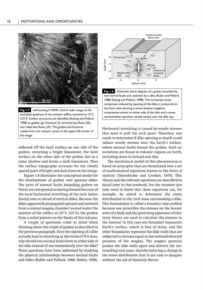
Figure 1.8 illustrates the conceptual model for
the development of graben over igneous dikes.
The pairs of normal faults bounding graben on
Venus are interpreted as having formed because of
the local horizontal stretching of the rock immediately over or ahead of vertical dikes. Because the
dikes apparently propagated upward and outward
from a central magma chamber located under the
summit of the edifice at (15Њ S, 215ЊE), the graben
form a radial pattern on the flanks of this volcano.
A couple of questions come to mind when
thinking about the origin of graben as described in
the previous paragraph. Does the opening of a dike
actually lead to stretching at the surface? If it does,
why should two normal faults form to either side of
the dike instead of one immediately over the dike?
These questions have been addressed by studying
the physical relationships between normal faults
and dikes (Rubin and Pollard, 1988; Rubin, 1990).
Horizontal stretching is caused by tensile stresses
that tend to pull the rock apart. Therefore, one
needs to determine if dike opening at depth could
induce tensile stresses near the Earth’s surface,
where normal faults bound the graben. Such associations are found in volcanic regions on Earth,
including those in Iceland and Afar.
The mechanical model of this phenomenon is
based on principles that are formulated into a set
of mathematical equations known as the theory of
elasticity (Timoshenko and Goodier, 1970). This
theory and the relevant equations are described in
detail later in this textbook. For the moment you
only need to know that these equations can, for
example, be solved to determine the stress
distribution in the rock mass surrounding a dike.
This formulation is called a boundary value problem
because one prescribes the stresses on the boundaries of a body and the governing equations of elasticity theory are used to calculate the stresses in
the interior. In this case one boundary represents
Earth’s surface, which is free of stress, and the
other boundaries represent the dike walls that are
subjected to stresses equal to the outward-directed
pressure of the magma. The magma pressure
pushes the dike walls apart and distorts the surrounding rock mass, thereby inducing a change in
the stress distribution that is not easy to imagine
without the aid of elasticity theory.
10
MOTIVATIONS AND OPPORTUNITIES
50 km
f
tlf
rlf
g
Fig 1.7 Left-looking F-MIDR 15s214 radar image of the
southeast quadrant of the volcanic edifice centered at 15ЊS,
215ЊE. Surface structures are identified (Koenig and Pollard,
1998) as graben (g), fractures (f), terminal lava flows (tlf ),
and radial lava flows (rlf ). The graben and fractures
radiate from the volcanic center in the upper left corner of
the image.
0.0
0.0
–5
0
5
–2
–4
–6
–8
Graben formed
above dike
Depth (km)
Distance (km)
–0.2
–0.4
0.0
0.2
0.4
0.0
0.2
0.4
–0.4
0.0
–0.2
0.0
Contours of
horizontal
stress
Magma-filled
dike
Normal fault
Fig 1.8 Schematic block diagram of a graben bounded by
two normal faults and underlain by a dike (Rubin and Pollard,
1988; Koenig and Pollard, 1998). The horizontal stress
component induced by opening of the dike is contoured on
the front view showing a stress shadow (negative,
compressive stress) to either side of the dike and a stress
concentration (positive, tensile stress) near the dike tips.
graben, returning a bright lineament, the fault
surface on the other side of the graben lies in a
radar shadow and forms a dark lineament. Thus
the surface topography accounts for the closely
spaced pairs of bright and dark lines on the image.
Figure 1.8 illustrates the conceptual model for
the development of graben over igneous dikes.
The pairs of normal faults bounding graben on
Venus are interpreted as having formed because of
the local horizontal stretching of the rock immediately over or ahead of vertical dikes. Because the
dikes apparently propagated upward and outward
from a central magma chamber located under the
summit of the edifice at (15Њ S, 215ЊE), the graben
form a radial pattern on the flanks of this volcano.
A couple of questions come to mind when
thinking about the origin of graben as described in
the previous paragraph. Does the opening of a dike
actually lead to stretching at the surface? If it does,
why should two normal faults form to either side of
the dike instead of one immediately over the dike?
These questions have been addressed by studying
the physical relationships between normal faults
and dikes (Rubin and Pollard, 1988; Rubin, 1990).
Horizontal stretching is caused by tensile stresses
that tend to pull the rock apart. Therefore, one
needs to determine if dike opening at depth could
induce tensile stresses near the Earth’s surface,
where normal faults bound the graben. Such associations are found in volcanic regions on Earth,
including those in Iceland and Afar.
The mechanical model of this phenomenon is
based on principles that are formulated into a set
of mathematical equations known as the theory of
elasticity (Timoshenko and Goodier, 1970). This
theory and the relevant equations are described in
detail later in this textbook. For the moment you
only need to know that these equations can, for
example, be solved to determine the stress
distribution in the rock mass surrounding a dike.
This formulation is called a boundary value problem
because one prescribes the stresses on the boundaries of a body and the governing equations of elasticity theory are used to calculate the stresses in
the interior. In this case one boundary represents
Earth’s surface, which is free of stress, and the
other boundaries represent the dike walls that are
subjected to stresses equal to the outward-directed
pressure of the magma. The magma pressure
pushes the dike walls apart and distorts the surrounding rock mass, thereby inducing a change in
the stress distribution that is not easy to imagine
without the aid of elasticity theory.
10
MOTIVATIONS AND OPPORTUNITIES
50 km
f
tlf
rlf
g
Fig 1.7 Left-looking F-MIDR 15s214 radar image of the
southeast quadrant of the volcanic edifice centered at 15ЊS,
215ЊE. Surface structures are identified (Koenig and Pollard,
1998) as graben (g), fractures (f), terminal lava flows (tlf ),
and radial lava flows (rlf ). The graben and fractures
radiate from the volcanic center in the upper left corner of
the image.
0.0
0.0
–5
0
5
–2
–4
–6
–8
Graben formed
above dike
Depth (km)
Distance (km)
–0.2
–0.4
0.0
0.2
0.4
0.0
0.2
0.4
–0.4
0.0
–0.2
0.0
Contours of
horizontal
stress
Magma-filled
dike
Normal fault
Fig 1.8 Schematic block diagram of a graben bounded by
two normal faults and underlain by a dike (Rubin and Pollard,
1988; Koenig and Pollard, 1998). The horizontal stress
component induced by opening of the dike is contoured on
the front view showing a stress shadow (negative,
compressive stress) to either side of the dike and a stress
concentration (positive, tensile stress) near the dike tips.