

I
n this chapter we define the relationships
among forces, tractions, and stresses. One of
the first concepts encountered in a physics
class is that of the resultant force, F, acting on a
particle with mass, m, and the associated linear
acceleration, a, of that particle in the direction
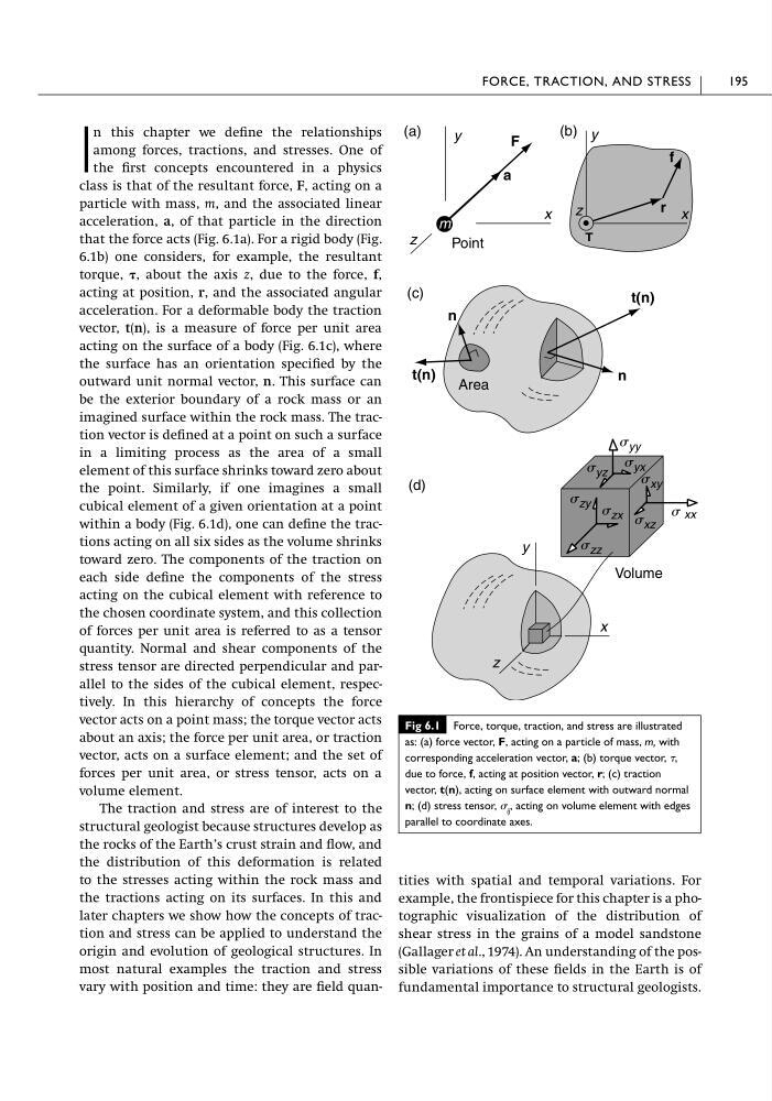
that the force acts (Fig. 6.1a). For a rigid body (Fig.
6.1b) one considers, for example, the resultant
torque, , about the axis z, due to the force, f,
acting at position, r, and the associated angular
acceleration. For a deformable body the traction
vector, t(n), is a measure of force per unit area
acting on the surface of a body (Fig. 6.1c), where
the surface has an orientation specified by the
outward unit normal vector, n. This surface can
be the exterior boundary of a rock mass or an
imagined surface within the rock mass. The traction vector is defined at a point on such a surface
in a limiting process as the area of a small
element of this surface shrinks toward zero about
the point. Similarly, if one imagines a small
cubical element of a given orientation at a point
within a body (Fig. 6.1d), one can define the tractions acting on all six sides as the volume shrinks
toward zero. The components of the traction on
each side define the components of the stress
acting on the cubical element with reference to
the chosen coordinate system, and this collection
of forces per unit area is referred to as a tensor
quantity. Normal and shear components of the
stress tensor are directed perpendicular and parallel to the sides of the cubical element, respectively. In this hierarchy of concepts the force
vector acts on a point mass; the torque vector acts
about an axis; the force per unit area, or traction
vector, acts on a surface element; and the set of
forces per unit area, or stress tensor, acts on a
volume element.
The traction and stress are of interest to the
structural geologist because structures develop as
the rocks of the Earth’s crust strain and flow, and
the distribution of this deformation is related
to the stresses acting within the rock mass and
the tractions acting on its surfaces. In this and
later chapters we show how the concepts of traction and stress can be applied to understand the
origin and evolution of geological structures. In
most natural examples the traction and stress
vary with position and time: they are field quantities with spatial and temporal variations. For
example, the frontispiece for this chapter is a photographic visualization of the distribution of
shear stress in the grains of a model sandstone
(Gallager et al., 1974). An understanding of the possible variations of these fields in the Earth is of
fundamental importance to structural geologists.
FORCE, TRACTION, AND STRESS
195
Fig 6.1 Force, torque, traction, and stress are illustrated
as: (a) force vector, F, acting on a particle of mass, m, with
corresponding acceleration vector, a; (b) torque vector, ,
due to force, f, acting at position vector, r; (c) traction
vector, t(n), acting on surface element with outward normal
n; (d) stress tensor, ij , acting on volume element with edges
parallel to coordinate axes.
S xx
x
y
(d)
x
y
F
a
(a)
n
n
(c)
z
z
Point
Area
Volume
m
t(n)
t(n)
S yy
S yz
S zy S zx
S zz
S xz
S xy
S yx
x
y
r
f
T
(b)
z
n this chapter we define the relationships
among forces, tractions, and stresses. One of
the first concepts encountered in a physics
class is that of the resultant force, F, acting on a
particle with mass, m, and the associated linear
acceleration, a, of that particle in the direction
that the force acts (Fig. 6.1a). For a rigid body (Fig.
6.1b) one considers, for example, the resultant
torque, , about the axis z, due to the force, f,
acting at position, r, and the associated angular
acceleration. For a deformable body the traction
vector, t(n), is a measure of force per unit area
acting on the surface of a body (Fig. 6.1c), where
the surface has an orientation specified by the
outward unit normal vector, n. This surface can
be the exterior boundary of a rock mass or an
imagined surface within the rock mass. The traction vector is defined at a point on such a surface
in a limiting process as the area of a small
element of this surface shrinks toward zero about
the point. Similarly, if one imagines a small
cubical element of a given orientation at a point
within a body (Fig. 6.1d), one can define the tractions acting on all six sides as the volume shrinks
toward zero. The components of the traction on
each side define the components of the stress
acting on the cubical element with reference to
the chosen coordinate system, and this collection
of forces per unit area is referred to as a tensor
quantity. Normal and shear components of the
stress tensor are directed perpendicular and parallel to the sides of the cubical element, respectively. In this hierarchy of concepts the force
vector acts on a point mass; the torque vector acts
about an axis; the force per unit area, or traction
vector, acts on a surface element; and the set of
forces per unit area, or stress tensor, acts on a
volume element.
The traction and stress are of interest to the
structural geologist because structures develop as
the rocks of the Earth’s crust strain and flow, and
the distribution of this deformation is related
to the stresses acting within the rock mass and
the tractions acting on its surfaces. In this and
later chapters we show how the concepts of traction and stress can be applied to understand the
origin and evolution of geological structures. In
most natural examples the traction and stress
vary with position and time: they are field quantities with spatial and temporal variations. For
example, the frontispiece for this chapter is a photographic visualization of the distribution of
shear stress in the grains of a model sandstone
(Gallager et al., 1974). An understanding of the possible variations of these fields in the Earth is of
fundamental importance to structural geologists.
FORCE, TRACTION, AND STRESS
195
Fig 6.1 Force, torque, traction, and stress are illustrated
as: (a) force vector, F, acting on a particle of mass, m, with
corresponding acceleration vector, a; (b) torque vector, ,
due to force, f, acting at position vector, r; (c) traction
vector, t(n), acting on surface element with outward normal
n; (d) stress tensor, ij , acting on volume element with edges
parallel to coordinate axes.
S xx
x
y
(d)
x
y
F
a
(a)
n
n
(c)
z
z
Point
Area
Volume
m
t(n)
t(n)
S yy
S yz
S zy S zx
S zz
S xz
S xy
S yx
x
y
r
f
T
(b)
z