

A linear transformation will take a circular
locus on the bed surface and transform it into an
ellipse. Since the long axis of the ellipse will lie
parallel to the cleavage and we know the angle
between the cleavage and the centerline of the
belemnite, we may try to compute the maximum
stretch from the stretch of the belemnite, l/l 0 ϭ
1.48 and the angle ␣ of 25Њ. We write the parametric equations for an ellipse as:
(5.1)
If the radius of the ellipse is 1.48 at ␣ ϭ 25Њ, we
have the relation:
(5.2)
Since this is only one equation in two unknowns,
we need further information or assumptions in
order to compute the maximum stretch. One
approach would be to find another, differently
oriented belemnite in the bedding plane, thus
providing another equation of the above form.
Another assumption is to suppose that an initial
unit circle of radius “one undeformed belemnite,”
a 2 cos 2 (25°) ϩ b 2 sin 2 (25°) ϭ (1.48) 2
y ϭ b sin ␣
x ϭ a cos ␣
was deformed to an ellipse with the same area. The
condition for this is that ab ϭ 1. Using this, a ϭ 1.61
and b ϭ 1/a ϭ 0.62. The ellipse, with lines representing the cleavage and belemnite, is shown in
Fig. 5.1b. If the cleavage were normal to the plane
of the drawing in Fig. 5.1a, the ellipse would be a
principal section of the strain ellipsoid, the threedimensional surface that would result from the
homogeneous deformation of a spherical surface.
Interpretation of naturally deformed objects to
yield the strain for some representative volume of
rock has a large literature in structural geology.
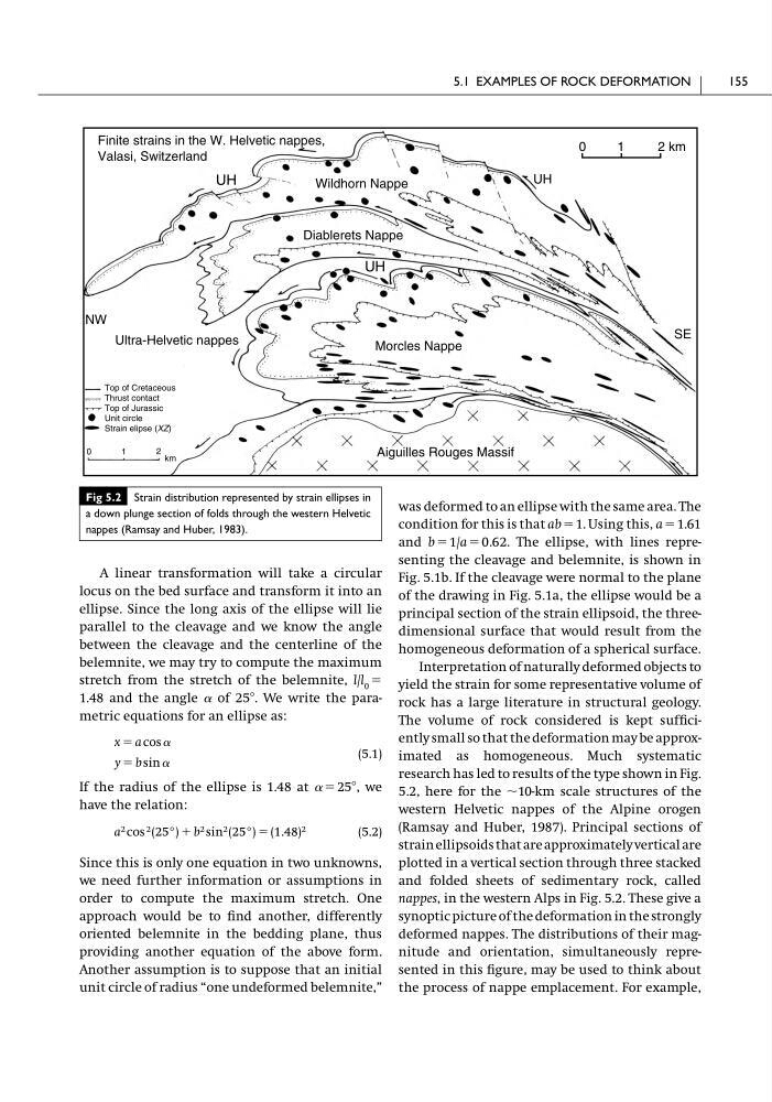
The volume of rock considered is kept sufficiently small so that the deformation may be approximated as homogeneous. Much systematic
research has led to results of the type shown in Fig.
5.2, here for the ϳ10-km scale structures of the
western Helvetic nappes of the Alpine orogen
(Ramsay and Huber, 1987). Principal sections of
strain ellipsoids that are approximately vertical are
plotted in a vertical section through three stacked
and folded sheets of sedimentary rock, called
nappes, in the western Alps in Fig. 5.2. These give a
synoptic picture of the deformation in the strongly
deformed nappes. The distributions of their magnitude and orientation, simultaneously represented in this figure, may be used to think about
the process of nappe emplacement. For example,
5.1 EXAMPLES OF ROCK DEFORMATION
155
Finite strains in the W. Helvetic nappes,
Valasi, Switzerland
Wildhorn Nappe
UH
0
1
2 km
SE
UH
UH
NW
Top of Cretaceous
Thrust contact
Top of Jurassic
Unit circle
Strain elipse (XZ)
0
1
2 km
Diablerets Nappe
Morcles Nappe
Ultra-Helvetic nappes
Aiguilles Rouges Massif
Fig 5.2 Strain distribution represented by strain ellipses in
a down plunge section of folds through the western Helvetic
nappes (Ramsay and Huber, 1983).
locus on the bed surface and transform it into an
ellipse. Since the long axis of the ellipse will lie
parallel to the cleavage and we know the angle
between the cleavage and the centerline of the
belemnite, we may try to compute the maximum
stretch from the stretch of the belemnite, l/l 0 ϭ
1.48 and the angle ␣ of 25Њ. We write the parametric equations for an ellipse as:
(5.1)
If the radius of the ellipse is 1.48 at ␣ ϭ 25Њ, we
have the relation:
(5.2)
Since this is only one equation in two unknowns,
we need further information or assumptions in
order to compute the maximum stretch. One
approach would be to find another, differently
oriented belemnite in the bedding plane, thus
providing another equation of the above form.
Another assumption is to suppose that an initial
unit circle of radius “one undeformed belemnite,”
a 2 cos 2 (25°) ϩ b 2 sin 2 (25°) ϭ (1.48) 2
y ϭ b sin ␣
x ϭ a cos ␣
was deformed to an ellipse with the same area. The
condition for this is that ab ϭ 1. Using this, a ϭ 1.61
and b ϭ 1/a ϭ 0.62. The ellipse, with lines representing the cleavage and belemnite, is shown in
Fig. 5.1b. If the cleavage were normal to the plane
of the drawing in Fig. 5.1a, the ellipse would be a
principal section of the strain ellipsoid, the threedimensional surface that would result from the
homogeneous deformation of a spherical surface.
Interpretation of naturally deformed objects to
yield the strain for some representative volume of
rock has a large literature in structural geology.
The volume of rock considered is kept sufficiently small so that the deformation may be approximated as homogeneous. Much systematic
research has led to results of the type shown in Fig.
5.2, here for the ϳ10-km scale structures of the
western Helvetic nappes of the Alpine orogen
(Ramsay and Huber, 1987). Principal sections of
strain ellipsoids that are approximately vertical are
plotted in a vertical section through three stacked
and folded sheets of sedimentary rock, called
nappes, in the western Alps in Fig. 5.2. These give a
synoptic picture of the deformation in the strongly
deformed nappes. The distributions of their magnitude and orientation, simultaneously represented in this figure, may be used to think about
the process of nappe emplacement. For example,
5.1 EXAMPLES OF ROCK DEFORMATION
155
Finite strains in the W. Helvetic nappes,
Valasi, Switzerland
Wildhorn Nappe
UH
0
1
2 km
SE
UH
UH
NW
Top of Cretaceous
Thrust contact
Top of Jurassic
Unit circle
Strain elipse (XZ)
0
1
2 km
Diablerets Nappe
Morcles Nappe
Ultra-Helvetic nappes
Aiguilles Rouges Massif
Fig 5.2 Strain distribution represented by strain ellipses in
a down plunge section of folds through the western Helvetic
nappes (Ramsay and Huber, 1983).