

characteristics of the device. In other words, regarding the out-coupling of light we
must impose the following condition on the device such that [7]
β 2 mK ¼ k 0 Á e e
ð
Þe e,
ð9:105Þ
where β is the propagation vector with |β| β that appeared in (8.153). The quantity
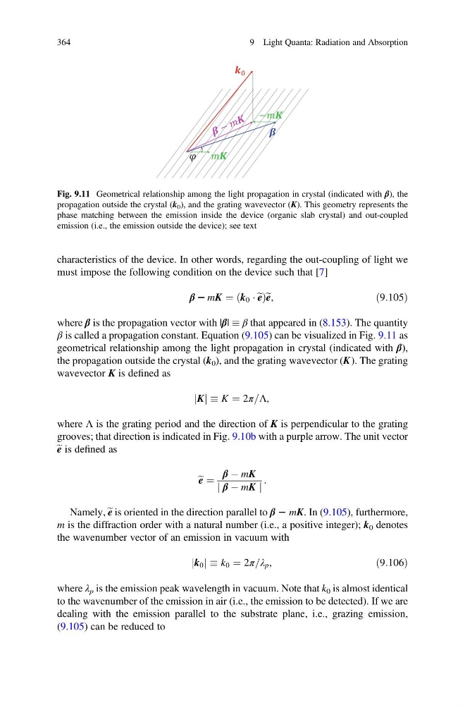
β is called a propagation constant. Equation (9.105) can be visualized in Fig. 9.11 as
geometrical relationship among the light propagation in crystal (indicated with β),
the propagation outside the crystal (k 0 ), and the grating wavevector (K ). The grating
wavevector K is defined as
K
j j K ¼ 2π=Λ,
where Λ is the grating period and the direction of K is perpendicular to the grating
grooves; that direction is indicated in Fig. 9.10b with a purple arrow. The unit vector
e e is defined as
e e ¼
β À mK
j β À mK j
:
Namely, e e is oriented in the direction parallel to β 2 mK. In (9.105), furthermore,
m is the diffraction order with a natural number (i.e., a positive integer); k 0 denotes
the wavenumber vector of an emission in vacuum with
k 0
j j k 0 ¼ 2π=λ p ,
ð9:106Þ
where λ p is the emission peak wavelength in vacuum. Note that k 0 is almost identical
to the wavenumber of the emission in air (i.e., the emission to be detected). If we are
dealing with the emission parallel to the substrate plane, i.e., grazing emission,
(9.105) can be reduced to
−
Fig. 9.11 Geometrical relationship among the light propagation in crystal (indicated with β), the
propagation outside the crystal (k 0 ), and the grating wavevector (K). This geometry represents the
phase matching between the emission inside the device (organic slab crystal) and out-coupled
emission (i.e., the emission outside the device); see text
364
9 Light Quanta: Radiation and Absorption
must impose the following condition on the device such that [7]
β 2 mK ¼ k 0 Á e e
ð
Þe e,
ð9:105Þ
where β is the propagation vector with |β| β that appeared in (8.153). The quantity
β is called a propagation constant. Equation (9.105) can be visualized in Fig. 9.11 as
geometrical relationship among the light propagation in crystal (indicated with β),
the propagation outside the crystal (k 0 ), and the grating wavevector (K ). The grating
wavevector K is defined as
K
j j K ¼ 2π=Λ,
where Λ is the grating period and the direction of K is perpendicular to the grating
grooves; that direction is indicated in Fig. 9.10b with a purple arrow. The unit vector
e e is defined as
e e ¼
β À mK
j β À mK j
:
Namely, e e is oriented in the direction parallel to β 2 mK. In (9.105), furthermore,
m is the diffraction order with a natural number (i.e., a positive integer); k 0 denotes
the wavenumber vector of an emission in vacuum with
k 0
j j k 0 ¼ 2π=λ p ,
ð9:106Þ
where λ p is the emission peak wavelength in vacuum. Note that k 0 is almost identical
to the wavenumber of the emission in air (i.e., the emission to be detected). If we are
dealing with the emission parallel to the substrate plane, i.e., grazing emission,
(9.105) can be reduced to
−
Fig. 9.11 Geometrical relationship among the light propagation in crystal (indicated with β), the
propagation outside the crystal (k 0 ), and the grating wavevector (K). This geometry represents the
phase matching between the emission inside the device (organic slab crystal) and out-coupled
emission (i.e., the emission outside the device); see text
364
9 Light Quanta: Radiation and Absorption