

x = rn þ su þ tv,
ð8:162Þ
where u and v represent unit vectors in the direction perpendicular to n. Then (8.161)
can be expressed by
E = E 0 e
i krÀωt
ð
Þ
:
ð8:163Þ
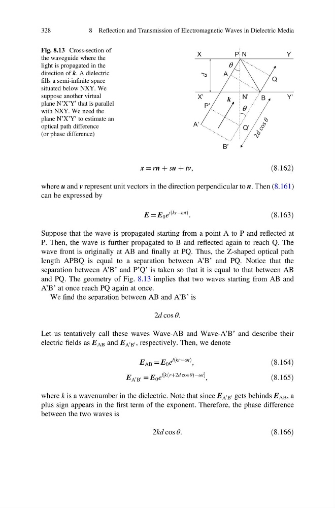
Suppose that the wave is propagated starting from a point A to P and reflected at
P. Then, the wave is further propagated to B and reflected again to reach Q. The
wave front is originally at AB and finally at PQ. Thus, the Z-shaped optical path
length APBQ is equal to a separation between A’B’ and PQ. Notice that the
separation between A’B’ and P’Q’ is taken so that it is equal to that between AB
and PQ. The geometry of Fig. 8.13 implies that two waves starting from AB and
A’B’ at once reach PQ again at once.
We find the separation between AB and A’B’ is
2d cos θ:
Let us tentatively call these waves Wave-AB and Wave-A’B’ and describe their
electric fields as E AB and E A
0 B
0 , respectively. Then, we denote
E AB = E 0 e
i krÀωt
ð
Þ ,
ð8:164Þ
E A
0 B
0 = E 0 e
i k rþ2d cos θ
ð
Þ À ωt
½
,
ð8:165Þ
where k is a wavenumber in the dielectric. Note that since E A
0 B
0 gets behinds E AB , a
plus sign appears in the first term of the exponent. Therefore, the phase difference
between the two waves is
2kd cos θ:
ð8:166Þ
θ
d
$
%
4
3
θ
$ಬ
%ಬ
4ಬ
3ಬ
1
<
;
1ಬ
<ಬ
;ಬ
Fig. 8.13 Cross-section of
the waveguide where the
light is propagated in the
direction of k. A dielectric
fills a semi-infinite space
situated below NXY. We
suppose another virtual
plane N’X’Y
0 that is parallel
with NXY. We need the
plane N’X’Y
0 to estimate an
optical path difference
(or phase difference)
328
8 Reflection and Transmission of Electromagnetic Waves in Dielectric Media
ð8:162Þ
where u and v represent unit vectors in the direction perpendicular to n. Then (8.161)
can be expressed by
E = E 0 e
i krÀωt
ð
Þ
:
ð8:163Þ
Suppose that the wave is propagated starting from a point A to P and reflected at
P. Then, the wave is further propagated to B and reflected again to reach Q. The
wave front is originally at AB and finally at PQ. Thus, the Z-shaped optical path
length APBQ is equal to a separation between A’B’ and PQ. Notice that the
separation between A’B’ and P’Q’ is taken so that it is equal to that between AB
and PQ. The geometry of Fig. 8.13 implies that two waves starting from AB and
A’B’ at once reach PQ again at once.
We find the separation between AB and A’B’ is
2d cos θ:
Let us tentatively call these waves Wave-AB and Wave-A’B’ and describe their
electric fields as E AB and E A
0 B
0 , respectively. Then, we denote
E AB = E 0 e
i krÀωt
ð
Þ ,
ð8:164Þ
E A
0 B
0 = E 0 e
i k rþ2d cos θ
ð
Þ À ωt
½
,
ð8:165Þ
where k is a wavenumber in the dielectric. Note that since E A
0 B
0 gets behinds E AB , a
plus sign appears in the first term of the exponent. Therefore, the phase difference
between the two waves is
2kd cos θ:
ð8:166Þ
θ
d
$
%
4
3
θ
$ಬ
%ಬ
4ಬ
3ಬ
1
<
;
1ಬ
<ಬ
;ಬ
Fig. 8.13 Cross-section of
the waveguide where the
light is propagated in the
direction of k. A dielectric
fills a semi-infinite space
situated below NXY. We
suppose another virtual
plane N’X’Y
0 that is parallel
with NXY. We need the
plane N’X’Y
0 to estimate an
optical path difference
(or phase difference)
328
8 Reflection and Transmission of Electromagnetic Waves in Dielectric Media