

ÀR
k
E R
k
H þ T
k
E T
k
H
cos ϕ
cos θ
¼ 1:
ð8:80Þ
In both the TE and TM cases, we define reflectance R and transmittance T such that
R ÀR E R H ¼ R
2
E ¼ 2 j S r j =2 j S i j¼j S r j = j S i j ,
ð8:81Þ
where S r and S i are time-averaged Poynting vectors of the reflected wave and
incident waves, respectively. Also, we have
T T E T H
cos ϕ
cos θ
¼
2 j S t j
2 j S i j
cos ϕ
cos θ
¼
j S t j
j S i j
cos ϕ
cos θ
,
ð8:82Þ
where S t is a time-averaged Poynting vector of the transmitted wave. Thus, we have
R þ T ¼ 1:
ð8:83Þ
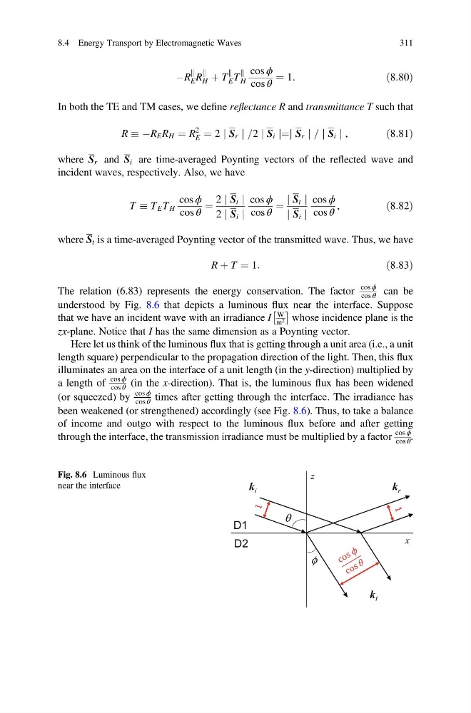
The relation (6.83) represents the energy conservation. The factor
cos ϕ
cos θ can be
understood by Fig. 8.6 that depicts a luminous flux near the interface. Suppose
that we have an incident wave with an irradiance I
W
m 2
 Ã
whose incidence plane is the
zx-plane. Notice that I has the same dimension as a Poynting vector.
Here let us think of the luminous flux that is getting through a unit area (i.e., a unit
length square) perpendicular to the propagation direction of the light. Then, this flux
illuminates an area on the interface of a unit length (in the y-direction) multiplied by
a length of
cos ϕ
cos θ (in the x-direction). That is, the luminous flux has been widened
(or squeezed) by
cos ϕ
cos θ times after getting through the interface. The irradiance has
been weakened (or strengthened) accordingly (see Fig. 8.6). Thus, to take a balance
of income and outgo with respect to the luminous flux before and after getting
through the interface, the transmission irradiance must be multiplied by a factor
cos ϕ
cos θ .
x
z
θ
φ
k i
k t
k r
'
'
Fig. 8.6 Luminous flux
near the interface
8.4 Energy Transport by Electromagnetic Waves
311
k
E R
k
H þ T
k
E T
k
H
cos ϕ
cos θ
¼ 1:
ð8:80Þ
In both the TE and TM cases, we define reflectance R and transmittance T such that
R ÀR E R H ¼ R
2
E ¼ 2 j S r j =2 j S i j¼j S r j = j S i j ,
ð8:81Þ
where S r and S i are time-averaged Poynting vectors of the reflected wave and
incident waves, respectively. Also, we have
T T E T H
cos ϕ
cos θ
¼
2 j S t j
2 j S i j
cos ϕ
cos θ
¼
j S t j
j S i j
cos ϕ
cos θ
,
ð8:82Þ
where S t is a time-averaged Poynting vector of the transmitted wave. Thus, we have
R þ T ¼ 1:
ð8:83Þ
The relation (6.83) represents the energy conservation. The factor
cos ϕ
cos θ can be
understood by Fig. 8.6 that depicts a luminous flux near the interface. Suppose
that we have an incident wave with an irradiance I
W
m 2
 Ã
whose incidence plane is the
zx-plane. Notice that I has the same dimension as a Poynting vector.
Here let us think of the luminous flux that is getting through a unit area (i.e., a unit
length square) perpendicular to the propagation direction of the light. Then, this flux
illuminates an area on the interface of a unit length (in the y-direction) multiplied by
a length of
cos ϕ
cos θ (in the x-direction). That is, the luminous flux has been widened
(or squeezed) by
cos ϕ
cos θ times after getting through the interface. The irradiance has
been weakened (or strengthened) accordingly (see Fig. 8.6). Thus, to take a balance
of income and outgo with respect to the luminous flux before and after getting
through the interface, the transmission irradiance must be multiplied by a factor
cos ϕ
cos θ .
x
z
θ
φ
k i
k t
k r
'
'
Fig. 8.6 Luminous flux
near the interface
8.4 Energy Transport by Electromagnetic Waves
311