

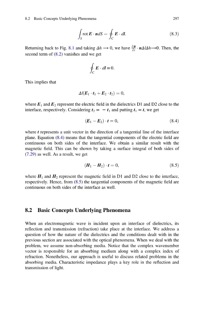
Z
S
rot E Á ndS ¼
I
C
E Á dl:
ð8:3Þ
Returning back to Fig. 8.1 and taking Δh ⟶ 0, we have
∂B
∂t
Á nΔlΔh⟶0. Then, the
second term of (8.2) vanishes and we get
I
C
E Á dl = 0:
This implies that
Δl E 1 Á t 1 þ E 2 Á t 2
ð
Þ ¼ 0,
where E 1 and E 2 represent the electric field in the dielectrics D1 and D2 close to the
interface, respectively. Considering t 2 = 2 t 1 and putting t 1 = t, we get
E 1 À E 2
ð
ÞÁt ¼ 0,
ð8:4Þ
where t represents a unit vector in the direction of a tangential line of the interface
plane. Equation (8.4) means that the tangential components of the electric field are
continuous on both sides of the interface. We obtain a similar result with the
magnetic field. This can be shown by taking a surface integral of both sides of
(7.29) as well. As a result, we get
H 1 À H 2
ð
ÞÁt ¼ 0,
ð8:5Þ
where H 1 and H 2 represent the magnetic field in D1 and D2 close to the interface,
respectively. Hence, from (8.5) the tangential components of the magnetic field are
continuous on both sides of the interface as well.
8.2 Basic Concepts Underlying Phenomena
When an electromagnetic wave is incident upon an interface of dielectrics, its
reflection and transmission (refraction) take place at the interface. We address a
question of how the nature of the dielectrics and the conditions dealt with in the
previous section are associated with the optical phenomena. When we deal with the
problem, we assume non-absorbing media. Notice that the complex wavenumber
vector is responsible for an absorbing medium along with a complex index of
refraction. Nonetheless, our approach is useful to discuss related problems in the
absorbing media. Characteristic impedance plays a key role in the reflection and
transmission of light.
8.2 Basic Concepts Underlying Phenomena
297
S
rot E Á ndS ¼
I
C
E Á dl:
ð8:3Þ
Returning back to Fig. 8.1 and taking Δh ⟶ 0, we have
∂B
∂t
Á nΔlΔh⟶0. Then, the
second term of (8.2) vanishes and we get
I
C
E Á dl = 0:
This implies that
Δl E 1 Á t 1 þ E 2 Á t 2
ð
Þ ¼ 0,
where E 1 and E 2 represent the electric field in the dielectrics D1 and D2 close to the
interface, respectively. Considering t 2 = 2 t 1 and putting t 1 = t, we get
E 1 À E 2
ð
ÞÁt ¼ 0,
ð8:4Þ
where t represents a unit vector in the direction of a tangential line of the interface
plane. Equation (8.4) means that the tangential components of the electric field are
continuous on both sides of the interface. We obtain a similar result with the
magnetic field. This can be shown by taking a surface integral of both sides of
(7.29) as well. As a result, we get
H 1 À H 2
ð
ÞÁt ¼ 0,
ð8:5Þ
where H 1 and H 2 represent the magnetic field in D1 and D2 close to the interface,
respectively. Hence, from (8.5) the tangential components of the magnetic field are
continuous on both sides of the interface as well.
8.2 Basic Concepts Underlying Phenomena
When an electromagnetic wave is incident upon an interface of dielectrics, its
reflection and transmission (refraction) take place at the interface. We address a
question of how the nature of the dielectrics and the conditions dealt with in the
previous section are associated with the optical phenomena. When we deal with the
problem, we assume non-absorbing media. Notice that the complex wavenumber
vector is responsible for an absorbing medium along with a complex index of
refraction. Nonetheless, our approach is useful to discuss related problems in the
absorbing media. Characteristic impedance plays a key role in the reflection and
transmission of light.
8.2 Basic Concepts Underlying Phenomena
297