

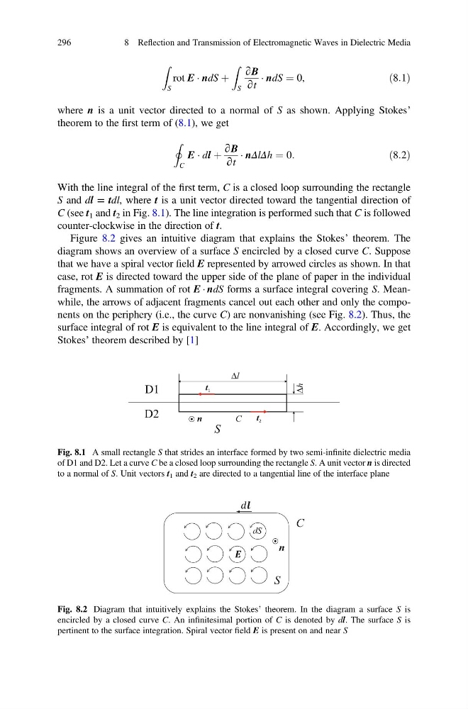
Z
S
rot E Á ndS þ
Z
S
∂B
∂t
Á ndS ¼ 0,
ð8:1Þ
where n is a unit vector directed to a normal of S as shown. Applying Stokes’
theorem to the first term of (8.1), we get
I
C
E Á dl þ
∂B
∂t
Á nΔlΔh ¼ 0:
ð8:2Þ
With the line integral of the first term, C is a closed loop surrounding the rectangle
S and dl = tdl, where t is a unit vector directed toward the tangential direction of
C (see t 1 and t 2 in Fig. 8.1). The line integration is performed such that C is followed
counter-clockwise in the direction of t.
Figure 8.2 gives an intuitive diagram that explains the Stokes’ theorem. The
diagram shows an overview of a surface S encircled by a closed curve C. Suppose
that we have a spiral vector field E represented by arrowed circles as shown. In that
case, rot E is directed toward the upper side of the plane of paper in the individual
fragments. A summation of rot E Á ndS forms a surface integral covering S. Meanwhile, the arrows of adjacent fragments cancel out each other and only the components on the periphery (i.e., the curve C) are nonvanishing (see Fig. 8.2). Thus, the
surface integral of rot E is equivalent to the line integral of E. Accordingly, we get
Stokes’ theorem described by [1]
Δl
Δh
D1
D2
t 1
t 2
n
S
C
Fig. 8.1 A small rectangle S that strides an interface formed by two semi-infinite dielectric media
of D1 and D2. Let a curve C be a closed loop surrounding the rectangle S. A unit vector n is directed
to a normal of S. Unit vectors t 1 and t 2 are directed to a tangential line of the interface plane
C
S
dS
n
Fig. 8.2 Diagram that intuitively explains the Stokes’ theorem. In the diagram a surface S is
encircled by a closed curve C. An infinitesimal portion of C is denoted by dl. The surface S is
pertinent to the surface integration. Spiral vector field E is present on and near S
296
8 Reflection and Transmission of Electromagnetic Waves in Dielectric Media
S
rot E Á ndS þ
Z
S
∂B
∂t
Á ndS ¼ 0,
ð8:1Þ
where n is a unit vector directed to a normal of S as shown. Applying Stokes’
theorem to the first term of (8.1), we get
I
C
E Á dl þ
∂B
∂t
Á nΔlΔh ¼ 0:
ð8:2Þ
With the line integral of the first term, C is a closed loop surrounding the rectangle
S and dl = tdl, where t is a unit vector directed toward the tangential direction of
C (see t 1 and t 2 in Fig. 8.1). The line integration is performed such that C is followed
counter-clockwise in the direction of t.
Figure 8.2 gives an intuitive diagram that explains the Stokes’ theorem. The
diagram shows an overview of a surface S encircled by a closed curve C. Suppose
that we have a spiral vector field E represented by arrowed circles as shown. In that
case, rot E is directed toward the upper side of the plane of paper in the individual
fragments. A summation of rot E Á ndS forms a surface integral covering S. Meanwhile, the arrows of adjacent fragments cancel out each other and only the components on the periphery (i.e., the curve C) are nonvanishing (see Fig. 8.2). Thus, the
surface integral of rot E is equivalent to the line integral of E. Accordingly, we get
Stokes’ theorem described by [1]
Δl
Δh
D1
D2
t 1
t 2
n
S
C
Fig. 8.1 A small rectangle S that strides an interface formed by two semi-infinite dielectric media
of D1 and D2. Let a curve C be a closed loop surrounding the rectangle S. A unit vector n is directed
to a normal of S. Unit vectors t 1 and t 2 are directed to a tangential line of the interface plane
C
S
dS
n
Fig. 8.2 Diagram that intuitively explains the Stokes’ theorem. In the diagram a surface S is
encircled by a closed curve C. An infinitesimal portion of C is denoted by dl. The surface S is
pertinent to the surface integration. Spiral vector field E is present on and near S
296
8 Reflection and Transmission of Electromagnetic Waves in Dielectric Media