

52
A. Geethakarthi
10μm
20μm
(b)
(a)
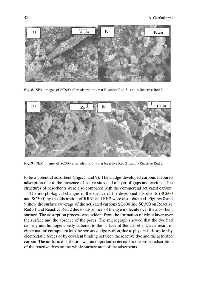
Fig. 8 SEM images of SC600 after adsorption on a Reactive Red 31 and b Reactive Red 2
10μm
10μm
(b)
(a)
Fig. 9 SEM images of SC300 after adsorption on a Reactive Red 31 and b Reactive Red 2
to be a potential adsorbent (Figs. 5 and 9). The sludge-developed carbons favoured
adsorption due to the presence of active sites and a layer of gaps and cavities. The
structures of adsorbents were also compared with the commercial activated carbon.
The morphological changes in the surface of the developed adsorbents (SC600
and SC300) by the adsorption of RR31 and RR2 were also obtained. Figures 8 and
9 show the surface coverage of the activated carbons SC600 and SC300 on Reactive
Red 31 and Reactive Red 2 due to adsorption of the dye molecule over the adsorbent
surface. The adsorption process was evident from the formation of white layer over
the surface and the absence of the pores. The micrograph showed that the dye had
densely and homogeneously adhered to the surface of the adsorbent, as a result of
either natural entrapment into the porous sludge carbon, due to physical adsorption by
electrostatic forces or by covalent binding between the reactive dye and the activated
carbon. The uniform distribution was an important criterion for the proper adsorption
of the reactive dyes on the whole surface area of the adsorbents.
A. Geethakarthi
10μm
20μm
(b)
(a)
Fig. 8 SEM images of SC600 after adsorption on a Reactive Red 31 and b Reactive Red 2
10μm
10μm
(b)
(a)
Fig. 9 SEM images of SC300 after adsorption on a Reactive Red 31 and b Reactive Red 2
to be a potential adsorbent (Figs. 5 and 9). The sludge-developed carbons favoured
adsorption due to the presence of active sites and a layer of gaps and cavities. The
structures of adsorbents were also compared with the commercial activated carbon.
The morphological changes in the surface of the developed adsorbents (SC600
and SC300) by the adsorption of RR31 and RR2 were also obtained. Figures 8 and
9 show the surface coverage of the activated carbons SC600 and SC300 on Reactive
Red 31 and Reactive Red 2 due to adsorption of the dye molecule over the adsorbent
surface. The adsorption process was evident from the formation of white layer over
the surface and the absence of the pores. The micrograph showed that the dye had
densely and homogeneously adhered to the surface of the adsorbent, as a result of
either natural entrapment into the porous sludge carbon, due to physical adsorption by
electrostatic forces or by covalent binding between the reactive dye and the activated
carbon. The uniform distribution was an important criterion for the proper adsorption
of the reactive dyes on the whole surface area of the adsorbents.