

Photo-Catalytic-Assisted Method for Treating Industrial …
163
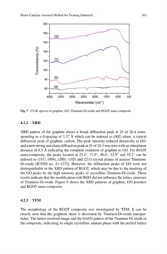
Fig. 7 FT-IR spectra of graphite, GO, Titanium-Di-oxide and RGOT nano-composite
4.2.2 XRD
XRD pattern of the graphite shows a broad diffraction peak at 2θ of 26.4 corresponding to a d-spacing of 3.37 Å which can be indexed to (002) plane, a typical
diffraction peak of graphitic carbon. The peak intensity reduced drastically in GO,
and a new strong and sharp diffraction peak at 2θ of 10.3 was seen with an interplanar
distance of 8.5 Å indicating the complete oxidation of graphite to GO. For RGOT
nano-composite, the peaks located at 25.4°, 37.9°, 48.0°, 53.9° and 55.2° can be
indexed to (101), (004), (200), (105) and (211) crystal planes of anatase TitaniumDi-oxide [JCPDS no. 21-1272]. However, the diffraction peaks of GO were not
distinguishable in the XRD pattern of RGOT, which may be due to the masking of
the GO peaks by the high intensity peaks of crystalline Titanium-Di-oxide. These
results indicate that the modification with RGO did not influence the lattice structure
of Titanium-Di-oxide. Figure 8 shows the XRD patterns of graphite, GO powders
and RGOT nano-composite.
4.2.3 TEM
The morphology of the RGOT composite was investigated by TEM. It can be
clearly seen that the graphene sheet is decorated by Titanium-Di-oxide nanoparticles. The lattice resolved image and the SAED pattern of the Titanium-Di-oxide in
the composite, indicating its single crystalline anatase phase with the perfect lattice
163
Fig. 7 FT-IR spectra of graphite, GO, Titanium-Di-oxide and RGOT nano-composite
4.2.2 XRD
XRD pattern of the graphite shows a broad diffraction peak at 2θ of 26.4 corresponding to a d-spacing of 3.37 Å which can be indexed to (002) plane, a typical
diffraction peak of graphitic carbon. The peak intensity reduced drastically in GO,
and a new strong and sharp diffraction peak at 2θ of 10.3 was seen with an interplanar
distance of 8.5 Å indicating the complete oxidation of graphite to GO. For RGOT
nano-composite, the peaks located at 25.4°, 37.9°, 48.0°, 53.9° and 55.2° can be
indexed to (101), (004), (200), (105) and (211) crystal planes of anatase TitaniumDi-oxide [JCPDS no. 21-1272]. However, the diffraction peaks of GO were not
distinguishable in the XRD pattern of RGOT, which may be due to the masking of
the GO peaks by the high intensity peaks of crystalline Titanium-Di-oxide. These
results indicate that the modification with RGO did not influence the lattice structure
of Titanium-Di-oxide. Figure 8 shows the XRD patterns of graphite, GO powders
and RGOT nano-composite.
4.2.3 TEM
The morphology of the RGOT composite was investigated by TEM. It can be
clearly seen that the graphene sheet is decorated by Titanium-Di-oxide nanoparticles. The lattice resolved image and the SAED pattern of the Titanium-Di-oxide in
the composite, indicating its single crystalline anatase phase with the perfect lattice