

χ ¼ À2
f χ
ð Þ À f 0
ð Þ
f 0
ð Þ
ð30:6Þ
The device developed for the evaluation of nZVI mobility is able to measure
values of the numerator and denominator of Eq. 30.6.
The entire LC circuit is integrated directly in the measuring head. The device
measures the frequency change of the LC circuit, which operates at frequency of
approximately 4 kHz and is able to measure changes at the level of units of mHz. The
device is equipped with a software, which allows to (i) control the drive unit of the
measuring head on the basis of the selected program, (ii) repeat measurements at
predetermined intervals, (iii) change the speed of the measuring head, and
(iv) collect and store data from the analyzer.
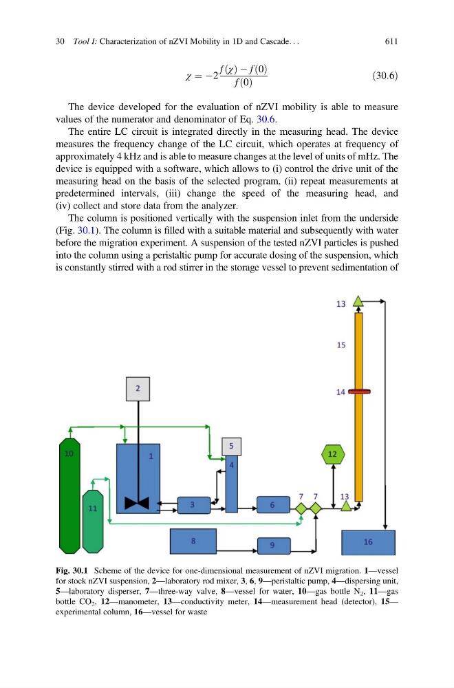
The column is positioned vertically with the suspension inlet from the underside
(Fig. 30.1). The column is filled with a suitable material and subsequently with water
before the migration experiment. A suspension of the tested nZVI particles is pushed
into the column using a peristaltic pump for accurate dosing of the suspension, which
is constantly stirred with a rod stirrer in the storage vessel to prevent sedimentation of
Fig. 30.1 Scheme of the device for one-dimensional measurement of nZVI migration. 1—vessel
for stock nZVI suspension, 2—laboratory rod mixer, 3, 6, 9—peristaltic pump, 4—dispersing unit,
5—laboratory disperser, 7—three-way valve, 8—vessel for water, 10—gas bottle N 2 , 11—gas
bottle CO 2 , 12—manometer, 13—conductivity meter, 14—measurement head (detector), 15—
experimental column, 16—vessel for waste
30 Tool I: Characterization of nZVI Mobility in 1D and Cascade. . .
611